Infiniti M35/M45 Y50. Manual — part 1011
REAR DRIVE SHAFT
RAX-13
C
E
F
G
H
I
J
K
L
M
A
B
RAX
2.
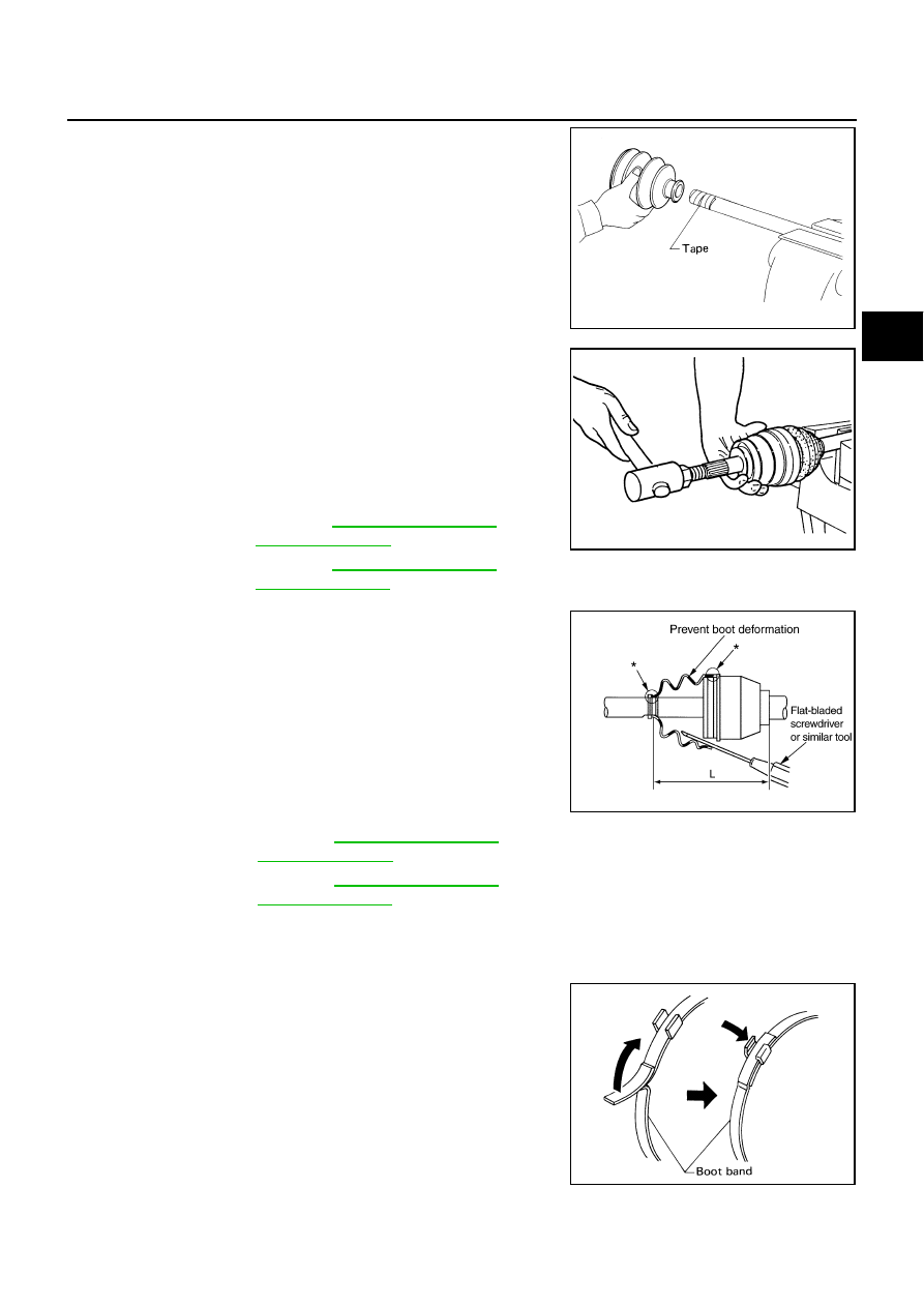
Wrap serrated part of shaft with tape. Install boot band and boot
to shaft. Be careful not to damage boot.
CAUTION:
Do not reuse boot band and boot.
3.
Remove protective tape wrapped around serrated part of shaft.
4.
Attach circular clip to shaft. At this time, circular clip must fit
securely into shaft groove. Attach nut to joint sub-assembly.
Use a wooden hammer to press-fit.
CAUTION:
Do not reuse circular clip.
5.
Apply the specified amount of grease (NISSAN genuine grease
or equivalent) into housing from large end of boot.
6.
Install boot securely into grooves (indicated by *marks) shown in
the figure.
CAUTION:
If there is grease on boot mounting surfaces (indicated by *
marks) of shaft and housing, boot may come off. Remove
all grease from the surfaces.
7.
Make sure boot installation length “L” is the length indicated
below. Insert a flat-bladed screwdriver or similar tool into inside
of boot from the large diameter side of the boot. Bleed air from
boot to prevent boot deformation.
CAUTION:
●
Boot may brake if boot installation length is less than standard value.
●
Be careful that screwdriver tip does not contact inside surface of boot.
8.
Secure large and small ends of boot with new boot bands as
shown in the figure.
CAUTION:
Do not reuse boot band.
9.
After installing joint sub-assembly and shaft, rotate boot to check
whether or not the actual position is correct. If boot position is
not correct, secure boot with new boot bands again.
10. Install dust shield to drive shaft.
CAUTION:
Do not reuse dust shield.
SFA800
Grease amount
VQ35DE model
: Refer to
VK45DE model
: Refer to
RAC0049D
Boot installation Length “L ”
VQ35DE model
: Refer to
VK45DE model
: Refer to
.
SDIA3250E
SFA395
RAX-14
SERVICE DATA AND SPECIFICATIONS (SDS)
SERVICE DATA AND SPECIFICATIONS (SDS)
PFP:00030
Wheel Bearing
NDS000FU
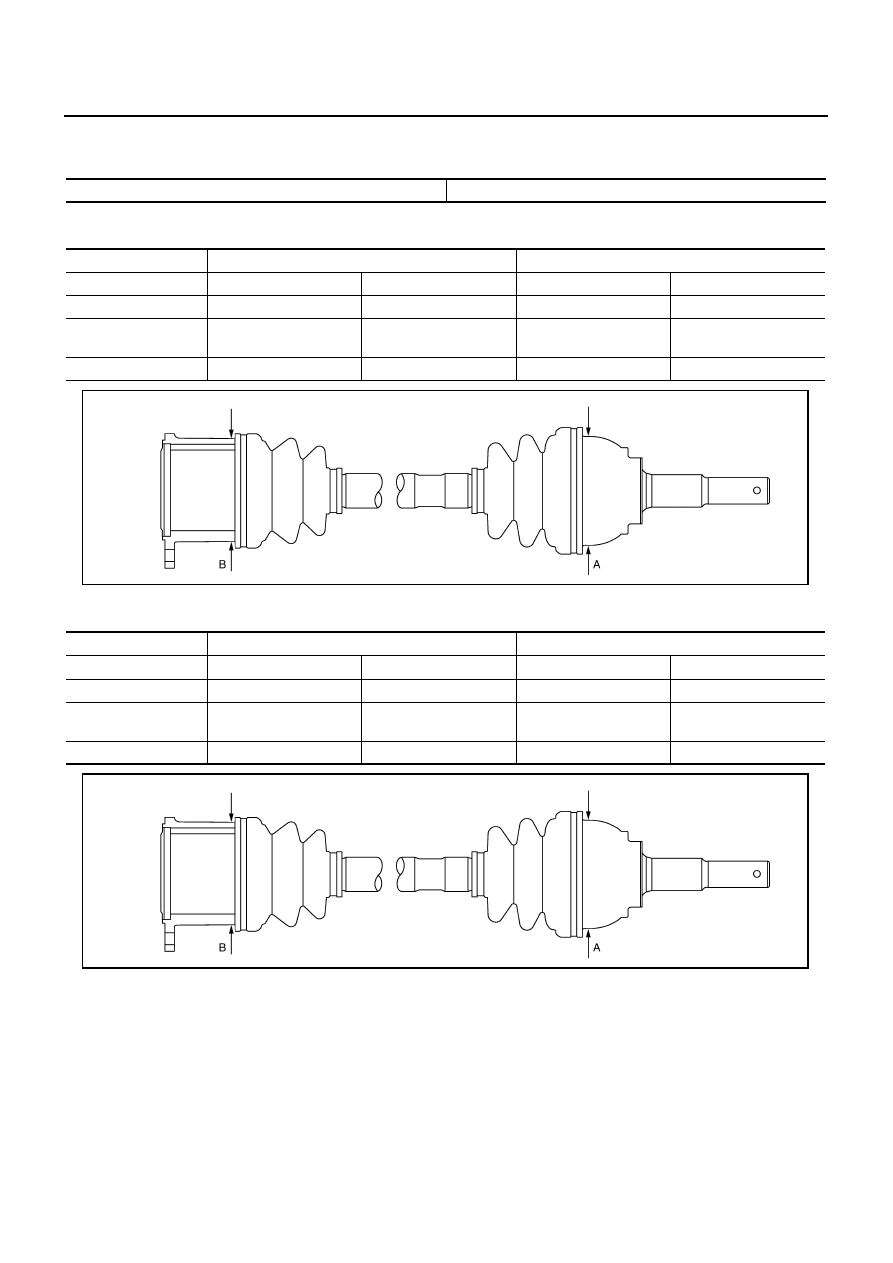
Drive Shaft (VQ35DE model)
NDS000GC
Since drive shafts vary with vehicle, carefully identify outside diameter (A) of joint sub-assembly and (B) of housing.
Drive Shaft (VK45DE model)
NDS000GD
Since drive shafts vary with vehicle, carefully identify outside diameter (A) of joint sub-assembly and (B) of housing.
Axial end play
0.05 mm (0.002 in) or less
Joint type
Wheel side
Final drive side
Outer diameter (A)
97.0 mm (3.819 in)
87.4 mm (3.441 in)
—
—
Outer diameter (B)
—
—
91.0 mm (3.583 in)
85.5 mm (3.366 in)
Grease quantity
115 – 135 g
(4.06 – 4.76 oz)
110 – 130 g
(3.87 – 4.59 oz)
130 – 150 g
(4.59 – 5.29 oz)
105 – 125 g
(3.70 – 4.40 oz)
Boots installed length
136 mm (5.354 in)
133 mm (5.236 in)
145 mm (5.709 in)
133 mm (5.236 in)
PDIA1280E
Joint type
Wheel side
Final drive side
Outer diameter (A)
97.0 mm (3.819 in)
87.4 mm (3.441 in)
—
—
Outer diameter (B)
—
—
91.0 mm (3.583 in)
85.5 mm (3.366 in)
Grease quantity
155 – 175 g
(5.47 – 6.12 oz)
110 – 130 g
(3.87 – 4.59 in)
155 – 175 g
(5.47 – 6.12 oz)
140 – 160 g
(4.94 – 5.64 oz)
Boots installed length
145 mm (5.709 in)
136 mm (5.354 in)
148 mm (5.827 in)
148 mm (5.827 in)
PDIA1280E
RF-1
ROOF
I BODY
CONTENTS
C
D
E
F
G
H
J
K
L
M
SECTION
RF
A
B
RF
ROOF
PRECAUTIONS . . . . . . . . . . . . . . .. 2
PREPARATION . . . . . . . . . . . . . . ... 3
Special Service Tools . . . . . . . . . . . ... 3
Commercial Service Tools . . . . . . . . . . 3
SQUEAK AND RATTLE TROUBLE DIAGNOSES . . 4
Work Flow . . . . . . . . . . . . . . . . 4
Generic Squeak and Rattle Troubleshooting . . ... 6
Diagnostic Worksheet . . . . . . . . . . . .. 8
SUNROOF . . . . . . . . . . . . . . . . 10
Component Parts and Harness Connector Location
System Description . . . . . . . . . . . . .11
TILT UP / SLIDE CLOSE OPERATION . . . . 11
Removal and Installation . . . . . . . . . . 24
SUNROOF UNIT . . . . . . . . . . . . . 26
Disassembly and Assembly . . . . . . . . . 27
DISASSEMBLY . . . . . . . . . . . . ... 28
ASSEMBLY . . . . . . . . . . . . . . . 28
RF-2
PRECAUTIONS
PRECAUTIONS
PFP:00001
Precautions for Supplemental Restraint System (SRS) “AIR BAG” and “SEAT
BELT PRE-TENSIONER”
NIS0023J
The Supplemental Restraint System such as “AIR BAG” and “SEAT BELT PRE-TENSIONER”, used along
with a front seat belt, helps to reduce the risk or severity of injury to the driver and front passenger for certain
types of collision. This system includes seat belt switch inputs and dual stage front air bag modules. The SRS
system uses the seat belt switches to determine the front air bag deployment, and may only deploy one front
air bag, depending on the severity of a collision and whether the front occupants are belted or unbelted.
Information necessary to service the system safely is included in the SRS and SB section of this Service Man-
ual.
WARNING:
●
To avoid rendering the SRS inoperative, which could increase the risk of personal injury or death
in the event of a collision which would result in air bag inflation, all maintenance must be per-
formed by an authorized NISSAN/INFINITI dealer.
●
Improper maintenance, including incorrect removal and installation of the SRS, can lead to per-
sonal injury caused by unintentional activation of the system. For removal of Spiral Cable and Air
Bag Module, see the SRS section.
●
Do not use electrical test equipment on any circuit related to the SRS unless instructed to in this
Service Manual. SRS wiring harnesses can be identified by yellow and/or orange harnesses or
harness connectors.
Precautions
NIS0023K
●
Disconnect both battery cables in advance.
●
Disconnect air bag system line in advance.
●
Do not tamper with or force air bag lid open, as this may adversely affect air bag performance.
●
Be careful not to scratch pad and other parts.
●
When removing or disassembling any part, be careful not to damage or deform it. Protect parts, which
may get in the way with cloth.
●
When removing parts with a screwdriver or other tool, protect parts by wrapping them with vinyl or tape.
●
Keep removed parts protected with cloth.
●
If a clip is deformed or damaged, replace it.
●
If an unreusable part is removed, replace it with a new one.
●
Tighten bolts and nuts firmly to the specified torque.
●
After re-assembly has been completed, make sure each part functions correctly.
●
Remove stains in the following way.
Water-soluble stains:
Dip a soft cloth in warm water, and then squeeze it tightly. After wiping the stain, wipe with a soft dry cloth.
Oil stain:
Dissolve a synthetic detergent in warm water (density of 2 to 3% or less), dip the cloth, then clean off the stain
with the cloth. Next, dip the cloth in fresh water and squeeze it tightly. Then clean off the detergent completely.
Then wipe the area with a soft dry cloth.
●
Do not use any organic solvent, such as thinner or benzine.
Нет комментариевНе стесняйтесь поделиться с нами вашим ценным мнением.
Текст