Infiniti M35/M45 Y50. Manual — part 542
DTC P2138 APP SENSOR
EC-641
[VQ35DE]
C
D
E
F
G
H
I
J
K
L
M
A
EC
Specification data are reference values and are measured between each terminal and ground.
CAUTION:
Do not use ECM ground terminals when measuring input/output voltage. Doing so may result in dam-
age to the ECM's transistor. Use a ground other than ECM terminals, such as the ground.
Diagnostic Procedure
NBS0057E
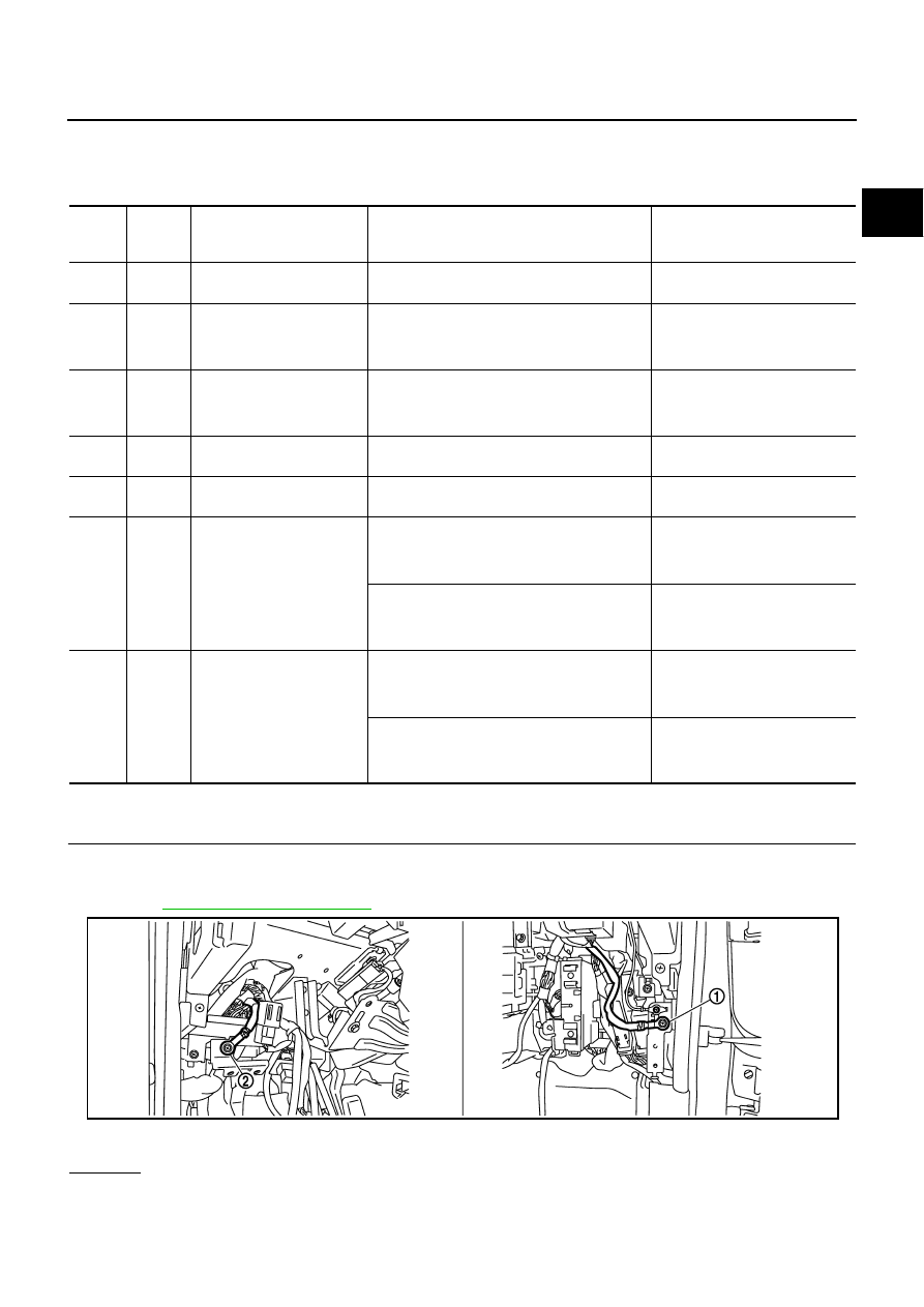
1.
CHECK GROUND CONNECTIONS
1.
Turn ignition switch OFF.
2.
Loosen and retighten two ground screws on the body.
Refer to
OK or NG
OK
>> GO TO 2.
NG
>> Repair or replace ground connections.
TER-
MINAL
NO.
WIRE
COLOR
ITEM
CONDITION
DATA (DC Voltage)
47
G
Sensor power supply
(Throttle position sensor)
[Ignition switch: ON]
Approximately 5V
82
W
Sensor ground
(APP sensor 1)
[Engine is running]
●
Warm-up condition
●
Idle speed
Approximately 0V
83
P
Sensor ground
(APP sensor 2)
[Engine is running]
●
Warm-up condition
●
Idle speed
Approximately 0V
90
L
Sensor power supply
(APP sensor 1)
[Ignition switch: ON]
Approximately 5V
91
BR
Sensor power supply
(APP sensor 2)
[Ignition switch: ON]
Approximately 5V
98
R
Accelerator pedal position
sensor 2
[Ignition switch: ON]
●
Engine stopped
●
Accelerator pedal: Fully released
0.20 - 0.55V
[Ignition switch: ON]
●
Engine stopped
●
Accelerator pedal: Fully depressed
1.85 - 2.40V
106
LG
Accelerator pedal position
sensor 1
[Ignition switch: ON]
●
Engine stopped
●
Accelerator pedal: Fully released
0.4 - 1.1V
[Ignition switch: ON]
●
Engine stopped
●
Accelerator pedal: Fully depressed
3.7 - 4.8V
1.
Body ground M70
2.
Body ground M16
PBIB2782E
EC-642
[VQ35DE]
DTC P2138 APP SENSOR
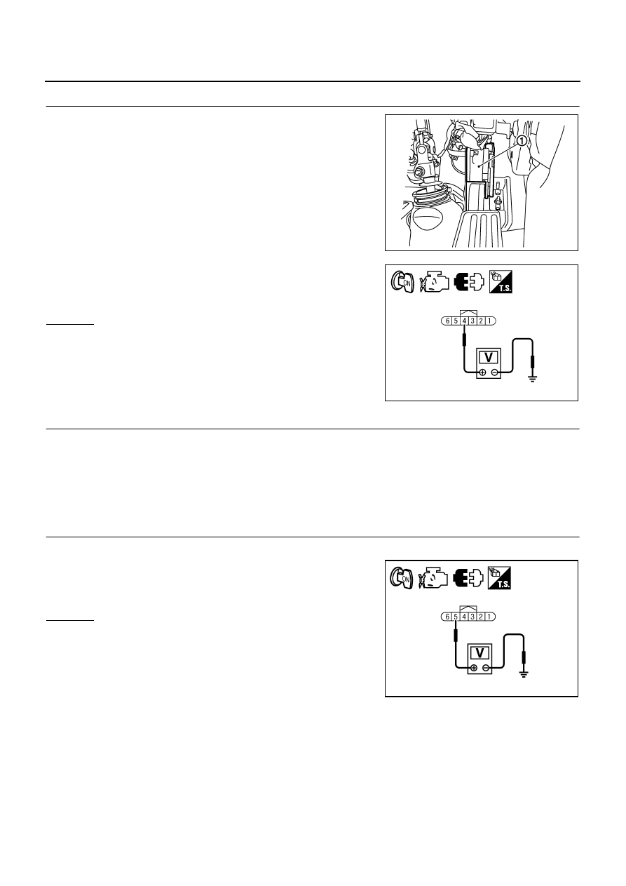
2.
CHECK APP SENSOR 1 POWER SUPPLY CIRCUIT
1.
Disconnect accelerator pedal position (APP) sensor (1) harness
connector.
2.
Turn ignition switch ON.
3.
Check voltage between APP sensor terminal 4 and ground with
CONSULT-II or tester.
OK or NG
OK
>> GO TO 4.
NG
>> GO TO 3.
3.
DETECT MALFUNCTIONING PART
Check the following.
●
Harness connectors E108, M15
●
Harness for open or short between ECM and accelerator pedal position sensor
>> Repair open circuit or short to ground or short to power in harness or connectors.
4.
CHECK APP SENSOR 2 POWER SUPPLY CIRCUIT-I
1.
Turn ignition switch ON.
2.
Check voltage between APP sensor terminal 5 and ground with
CONSULT-II or tester.
OK or NG
OK
>> GO TO 10.
NG
>> GO TO 5.
PBIB2704E
Voltage: Approximately 5V
PBIA9606J
Voltage: Approximately 5V
PBIA9607J

DTC P2138 APP SENSOR
EC-643
[VQ35DE]
C
D
E
F
G
H
I
J
K
L
M
A
EC
5.
CHECK APP SENSOR 2 POWER SUPPLY CIRCUIT-II
1.
Turn ignition switch OFF.
2.
Disconnect ECM harness connector.
3.
Check harness continuity between APP sensor terminal 5 and ECM terminal 91.
Refer to Wiring Diagram.
OK or NG
OK
>> GO TO 7.
NG
>> GO TO 6.
6.
DETECT MALFUNCTIONING PART
Check the following.
●
Harness connectors E108, M15
●
Harness for open or short between ECM and accelerator pedal position sensor
>> Repair open circuit.
7.
CHECK APP SENSOR 2 POWER SUPPLY CIRCUIT-III
Check harness for short to power and short to ground, between the following terminals.
OK or NG
OK
>> GO TO 8.
NG
>> Repair short to ground or short to power in harness or connectors.
8.
CHECK THROTTLE POSITION SENSOR
Refer to
EC-637, "Component Inspection"
OK or NG
OK
>> GO TO 16.
NG
>> GO TO 9.
9.
REPLACE ELECTRIC THROTTLE CONTROL ACTUATOR
1.
Replace the electric throttle control actuator.
2.
Perform
EC-86, "Throttle Valve Closed Position Learning"
3.
Perform
EC-86, "Idle Air Volume Learning"
>> INSPECTION END
Continuity should exist.
ECM terminal
Sensor terminal
Reference Wiring Diagram
91
APP sensor terminal 5
47
Electric throttle control actuator terminal 1
EC-644
[VQ35DE]
DTC P2138 APP SENSOR
10.
CHECK APP SENSOR GROUND CIRCUIT FOR OPEN AND SHORT
1.
Turn ignition switch OFF.
2.
Disconnect ECM harness connector.
3.
Check harness continuity between the following;
APP sensor terminal 2 and ECM terminal 82,
APP sensor terminal 1 and ECM terminal 83.
Refer to Wiring Diagram.
4.
Also check harness for short to ground and short to power.
OK or NG
OK
>> GO TO 12.
NG
>> GO TO 11.
11.
DETECT MALFUNCTIONING PART
Check the following.
●
Harness connectors E108, M15
●
Harness for open or short between ECM and accelerator pedal position sensor
>> Repair open circuit or short to ground or short to power in harness or connectors.
12.
CHECK APP SENSOR INPUT SIGNAL CIRCUIT FOR OPEN AND SHORT
1.
Check harness continuity between the following;
ECM terminal 106 and APP sensor terminal 3,
ECM terminal 98 and APP sensor terminal 6.
Refer to Wiring Diagram.
2.
Also check harness for short to ground and short to power.
OK or NG
OK
>> GO TO 14.
NG
>> GO TO 13.
13.
DETECT MALFUNCTIONING PART
Check the following.
●
Harness connectors E108, M15
●
Harness for open or short between ECM and accelerator pedal position sensor
>> Repair open circuit or short to ground or short to power in harness or connectors.
14.
CHECK APP SENSOR
Refer to
EC-645, "Component Inspection"
OK or NG
OK
>> GO TO 16.
NG
>> GO TO 15.
Continuity should exist.
Continuity should exist.
Нет комментариевНе стесняйтесь поделиться с нами вашим ценным мнением.
Текст