Infiniti M35/M45 Y50. Manual — part 730
FUEL INJECTOR
EC-1393
[VK45DE]
C
D
E
F
G
H
I
J
K
L
M
A
EC
3.
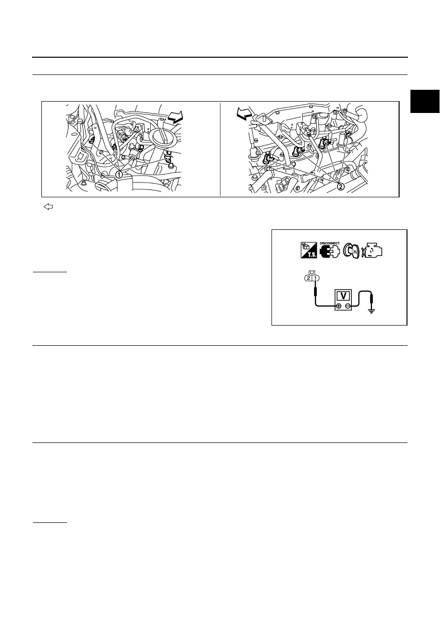
CHECK FUEL INJECTOR POWER SUPPLY CIRCUIT
1.
Turn ignition switch OFF.
2.
Disconnect fuel injector harness connectors.
3.
Turn ignition switch ON.
4.
Check voltage between fuel injector terminal 1 and ground with
CONSULT-II or tester.
OK or NG
OK
>> GO TO 5.
NG
>> GO TO 4.
4.
DETECT MALFUNCTIONING PART
Check the following.
●
Harness connectors M72, F102
●
Fuse block (J/B) connector M4
●
15A fuse
●
Harness for open or short between fuel injector and fuse
>> Repair open circuit or short to ground or short to power in harness or connectors.
5.
CHECK FUEL INJECTOR OUTPUT SIGNAL CIRCUIT FOR OPEN AND SHORT
1.
Turn ignition switch OFF.
2.
Disconnect ECM harness connector.
3.
Check harness continuity between ECM terminals 21, 22, 23, 40, 41, 42, 44, 63 and fuel injector terminal
2. Refer to Wiring Diagram.
4.
Also check harness for short to ground and short to power.
OK or NG
OK
>> GO TO 6.
NG
>> Repair open circuit or short to ground or short to power in harness or connectors.
: Vehicle front
1.
Fuel injector (bank 2)
2.
Fuel injector (bank 1)
Voltage: Battery voltage
PBIB2693E
PBIB0582E
Continuity should exist.
EC-1394
[VK45DE]
FUEL INJECTOR
6.
CHECK FUEL INJECTOR
Refer to
EC-1394, "Component Inspection"
OK or NG
OK
>> GO TO 7.
NG
>> Replace fuel injector.
7.
CHECK INTERMITTENT INCIDENT
Refer to
EC-857, "TROUBLE DIAGNOSIS FOR INTERMITTENT INCIDENT"
.
>> INSPECTION END
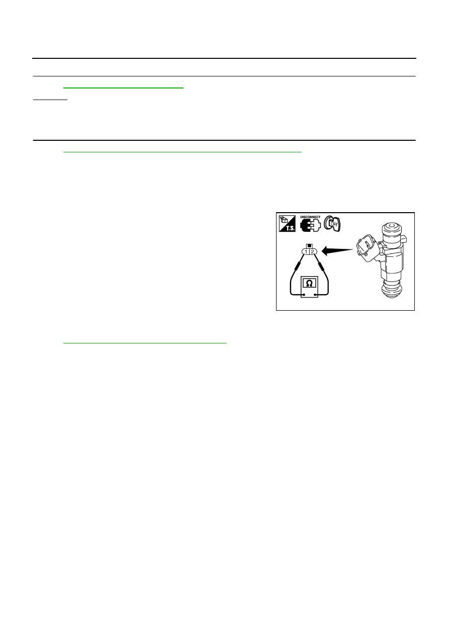
Component Inspection
NBS005PZ
FUEL INJECTOR
1.
Disconnect fuel injector harness connector.
2.
Check resistance between terminals as shown in the figure.
Removal and Installation
NBS005Q0
FUEL INJECTOR
Refer to
EM-193, "FUEL INJECTOR AND FUEL TUBE"
Resistance: 13.5 - 17.5
Ω
[at 10 - 60
°
C (50 - 140
°
F)]
PBIB1727E
FUEL PUMP
EC-1395
[VK45DE]
C
D
E
F
G
H
I
J
K
L
M
A
EC
FUEL PUMP
PFP:17042
Description
NBS005Q1
SYSTEM DESCRIPTION
*: ECM determines the start signal status by the signals of engine speed and battery voltage.
The ECM activates the fuel pump for several seconds after the ignition switch is turned ON to improve engine
startability. If the ECM receives a engine speed signal from the camshaft position sensor (PHASE), it knows
that the engine is rotating, and causes the pump to operate. If the engine speed signal is not received when
the ignition switch is ON, the engine stalls. The ECM stops pump operation and prevents battery discharging,
thereby improving safety. The ECM does not directly drive the fuel pump. It controls the ON/OFF fuel pump
relay, which in turn controls the fuel pump.
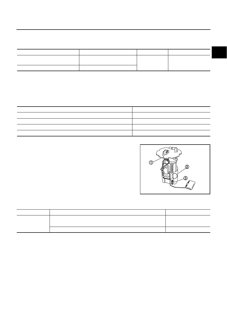
COMPONENT DESCRIPTION
A turbine type design fuel pump is used in the fuel tank.
●
Fuel level sensor unit and fuel pump (1)
●
Fuel pressure regulator (2)
●
Fuel tank temperature sensor (3)
CONSULT-II Reference Value in Data Monitor Mode
NBS005Q2
Specification data are reference values.
Sensor
Input signal to ECM
ECM Function
Actuator
Crankshaft position sensor (POS)
Camshaft position sensor (PHASE)
Engine speed*
Fuel pump control
Fuel pump relay
Battery
Battery voltage*
Condition
Fuel pump operation
Ignition switch is turned to ON.
Operates for 1 second.
Engine running and cranking
Operates.
When engine is stopped
Stops in 1.5 seconds.
Except as shown above
Stops.
PBIB2707E
MONITOR ITEM
CONDITION
SPECIFICATION
FUEL PUMP RLY
●
For 1 seconds after turning ignition switch: ON
●
Engine running or cranking
ON
●
Except above
OFF
EC-1396
[VK45DE]
FUEL PUMP
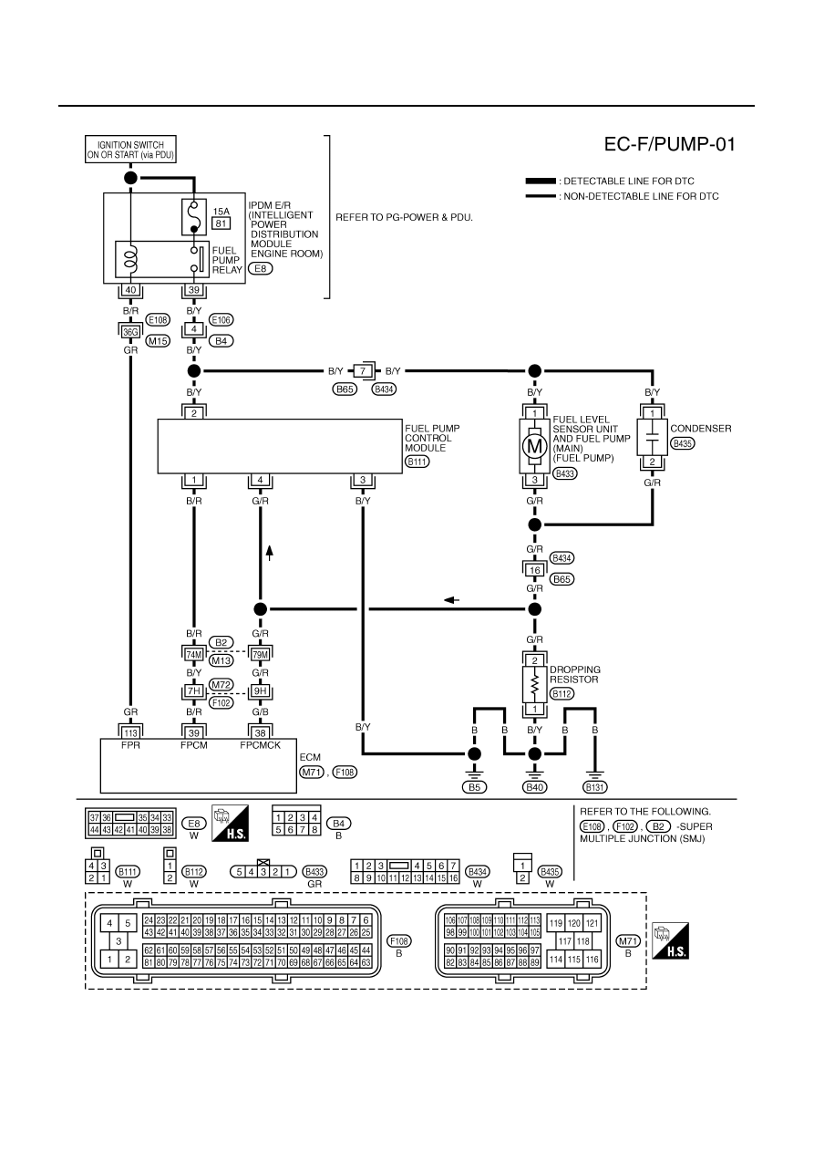
Wiring Diagram
NBS005Q3
TBWT1506E
Нет комментариевНе стесняйтесь поделиться с нами вашим ценным мнением.
Текст