Infiniti M35/M45 Y50. Manual — part 65

MAIN POWER SUPPLY AND GROUND CIRCUIT
AT-183
D
E
F
G
H
I
J
K
L
M
A
B
AT
7.
CHECK TERMINAL CORD ASSEMBLY
1.
Remove control valve with TCM. Refer to
AT-236, "Control Valve With TCM and A/T Fluid Temperature
.
2.
Disconnect A/T assembly harness connector and TCM connector.
3.
Check continuity between A/T assembly harness connector ter-
minals and TCM connector terminals.
4.
Check continuity between A/T assembly harness connector ter-
minals and TCM connector terminals.
5.
If OK, check harness for short to ground and short to power.
OK or NG
OK
>> Replace the control valve with TCM. Refer to
AT-236, "Control Valve With TCM and A/T Fluid
NG
>> Replace open circuit or short to ground and short to power in harness or connectors.
Item
Connector
Terminal
Continuity
A/T assembly harness con-
nector
F42
1
Yes
TCM connector
F502
9
A/T assembly harness con-
nector
F42
2
Yes
TCM connector
F502
10
A/T assembly harness con-
nector
F42
6
Yes
TCM connector
F502
4
SCIA5464E
Item
Connector
Terminal
Continuity
A/T assembly harness con-
nector
F42
5
Yes
TCM connector
F504
21
A/T assembly harness con-
nector
F42
10
Yes
TCM connector
F504
22
SCIA5465E
AT-184
CLOSED THROTTLE POSITION AND WIDE OPEN THROTTLE POSITION CIR-
CUIT
CLOSED THROTTLE POSITION AND WIDE OPEN THROTTLE POSITION CIR-
CUIT
PFP:18002
CONSULT-II Reference Value
NCS001PR
Diagnostic Procedure
NCS001PS
1.
CHECK CAN COMMUNICATION LINE
Perform the self-diagnosis. Refer to
AT-92, "SELF-DIAGNOSTIC RESULT MODE"
.
Is a malfunction in the CAN communication indicated in the results?
YES
>> Check CAN communication line. Refer to
AT-105, "DTC U1000 CAN COMMUNICATION LINE"
NO
>> GO TO 2.
2.
CHECK THROTTLE POSITION SIGNAL CIRCUIT
With CONSULT-II
1.
Turn ignition switch ON.
2.
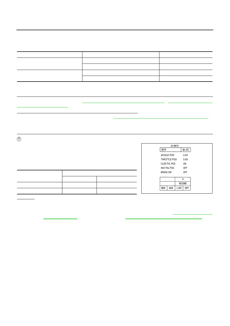
Select “ECU INPUT SIGNALS” in “DATA MONITOR” mode for
“A/T” with CONSULT-II.
3.
Depress accelerator pedal and read out the value of “CLSD THL
POS” and “W/O THL POS”.
OK or NG
OK
>> INSPECTION END
NG
>> Check the following. If NG, repair or replace damaged parts.
●
Perform the self-diagnosis for “ENGINE” with CONSULT-II. Refer to
(for VQ35DE engine),
EC-829, "SELF-DIAG RESULTS MODE"
(for
VK45DE engine).
●
Open circuit or short to ground or short to power in harness or connectors.
●
Pin terminals for damage or loose connection with harness connector.
Item name
Condition
Display value
CLSD THL POS
Released accelerator pedal.
ON
Fully depressed accelerator pedal.
OFF
W/O THL POS
Fully depressed accelerator pedal.
ON
Released accelerator pedal.
OFF
Accelerator Pedal Operation
Monitor Item
CLSD THL POS
W/O THL POS
Released
ON
OFF
Fully depressed
OFF
ON
PCIA0070E

BRAKE SIGNAL CIRCUIT
AT-185
D
E
F
G
H
I
J
K
L
M
A
B
AT
BRAKE SIGNAL CIRCUIT
PFP:25320
CONSULT-II Reference Value
NCS001PT
Diagnostic Procedure
NCS001PU
1.
CHECK CAN COMMUNICATION LINE
Perform the self-diagnosis. Refer to
AT-92, "SELF-DIAGNOSTIC RESULT MODE"
Is a malfunction in the CAN communication indicated in the results?
YES
>> Check CAN communication line. Refer to
AT-105, "DTC U1000 CAN COMMUNICATION LINE"
.
NO
>> GO TO 2.
2.
CHECK STOP LAMP SWITCH CIRCUIT
With CONSULT-II
1.
Turn ignition switch ON.
2.
Select “ECU INPUT SIGNALS” in “DATA MONITOR” mode for
“A/T” with CONSULT-II.
3.
Read out ON/OFF switching action of the “BRAKE SW”.
OK or NG
OK
>> INSPECTION END
NG
>> GO TO 3.
3.
CHECK STOP LAMP SWITCH
Check continuity between stop lamp switch harness connector termi-
nals. Refer to
AT-187, "Wiring Diagram — AT — NONDTC"
.
Check stop lamp switch after adjusting brake pedal — refer to
OK or NG
OK
>> Check the following. If NG, repair or replace damaged
parts.
●
Harness for short or open between battery and stop lamp switch.
●
Harness for short or open between stop lamp switch and unified meter and A/C amp.
●
10A fuse (No.20, located in fuse block).
NG
>> Repair or replace the stop lamp switch.
Item name
Condition
Display value
BRAKE SW
Depressed brake pedal.
ON
Released brake pedal.
OFF
Item name
Condition
Display value
BRAKE SW
Depressed brake pedal.
ON
Released brake pedal.
OFF
PCIA0070E
Condition
Continuity
When brake pedal is depressed
Yes
When brake pedal is released
No
SCIA4782E
AT-186
A/T INDICATOR CIRCUIT
A/T INDICATOR CIRCUIT
PFP:24810
Description
NCS001PV
TCM sends the switch signals to unified meter and A/C amp. By CAN communication line. Then manual mode
switch position is indicated on the A/T indicator.
CONSULT-II Reference Value
NCS001PW
Diagnostic Procedure
NCS001PX
1.
CHECK INPUT SIGNALS
With CONSULT-II
1.
Start engine.
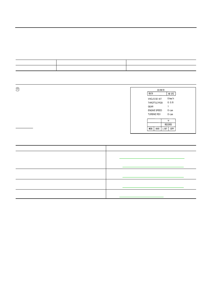
2.
Select “MAIN SIGNALS” in “DATA MONITOR” mode for “A/T”
with CONSULT-II and read out the value of “GEAR”.
3.
Drive vehicle in the manual mode, and confirm that the actual
gear position and the meter's indication of the position mutually
coincide when the selector lever is shifted to the “+ (up)” or “-
(down)” side (1st
⇔
5th gear).
OK or NG
OK
>> INSPECTION END
NG
>> Check the following.
A/T INDICATOR SYMPTOM CHART
Item name
Condition
Display value
GEAR
During driving
1, 2, 3, 4, 5
PCIA0065E
Items
Possible location of malfunction
The actual gear position does not change, or shifting into the
manual mode is not possible (no gear shifting in the manual mode
possible).
The A/T indicator is not indicated.
Manual mode switch
Refer to
AT-167, "DTC P1815 MANUAL MODE SWITCH"
.
A/T main system (Fail-safe function actuated)
●
Refer to
AT-92, "SELF-DIAGNOSTIC RESULT MODE"
.
The actual gear position changes, but the A/T indicator is not indi-
cated.
Perform the self-diagnosis function.
●
Refer to
AT-92, "SELF-DIAGNOSTIC RESULT MODE"
.
The actual gear position and the indication on the A/T indicator do
not coincide.
Perform the self-diagnosis function.
●
Refer to
AT-92, "SELF-DIAGNOSTIC RESULT MODE"
.
Only a specific position or positions is/are not indicated on the A/T
indicator.
Check the unified meter and A/C amp.
Refer to
Нет комментариевНе стесняйтесь поделиться с нами вашим ценным мнением.
Текст