Infiniti M35/M45 Y50. Manual — part 845
TROUBLE DIAGNOSES WORK FLOW
LAN-29
[CAN FUNDAMENTAL]
C
D
E
F
G
H
I
J
L
M
A
B
LAN
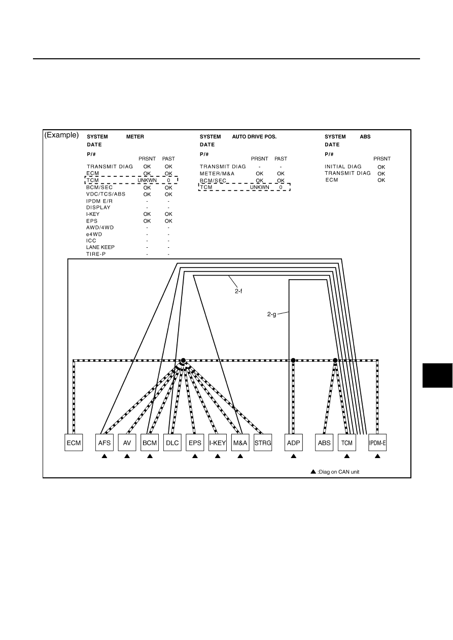
f.
Reception item of “METER”: On “TCM”, “UNKWN” is indicated. This means M&A cannot receive the sig-
nal from TCM. Draw a line to indicate an error between M&A and TCM (line 2-f in the figure).
g.
Reception item of “AUTO DRIVE POS.”: On “TCM”, “UNKWN” is indicated. This means ADP cannot
receive the signal from TCM. Draw a line to indicate an error between ADP and TCM (line 2-g in the fig-
ure).
h.
Reception item of “ABS”: “UNKWN” is not indicated. This indicates normal communication between ABS
and its receiving units. Do not draw any line.
SKIB8727E
LAN-30
[CAN FUNDAMENTAL]
TROUBLE DIAGNOSES WORK FLOW
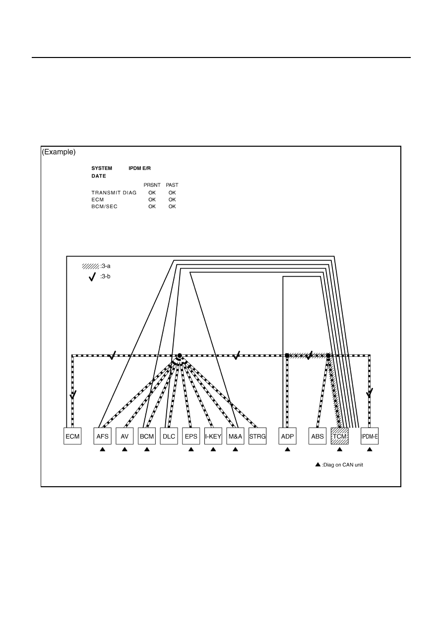
i.
Reception item of “IPDM E/R”: “UNKWN” is not indicated. This indicates normal communication between
IPDM-E and its receiving units. Do not draw any line.
3.
Based on information received from “CAN DIAG SUPPORT MNTR”, place a check mark on the known
good CAN communication line between ECM and IPDM-E.
a.
Through the previous procedure, the circuit between ADP splice and TCM has the most amount of lines
(shade 3-a in the figure).
b.
Place a check mark on the known good lines to establish the error circuit.
Reception item of “IPDM E/R”: On “ECM”, “OK” is indicated. IPDM-E communicates normally with ECM.
Put a check mark on the normal circuit between ECM and IPDM-E (check mark 3-b in the figure).
SKIB8728E
TROUBLE DIAGNOSES WORK FLOW
LAN-31
[CAN FUNDAMENTAL]
C
D
E
F
G
H
I
J
L
M
A
B
LAN
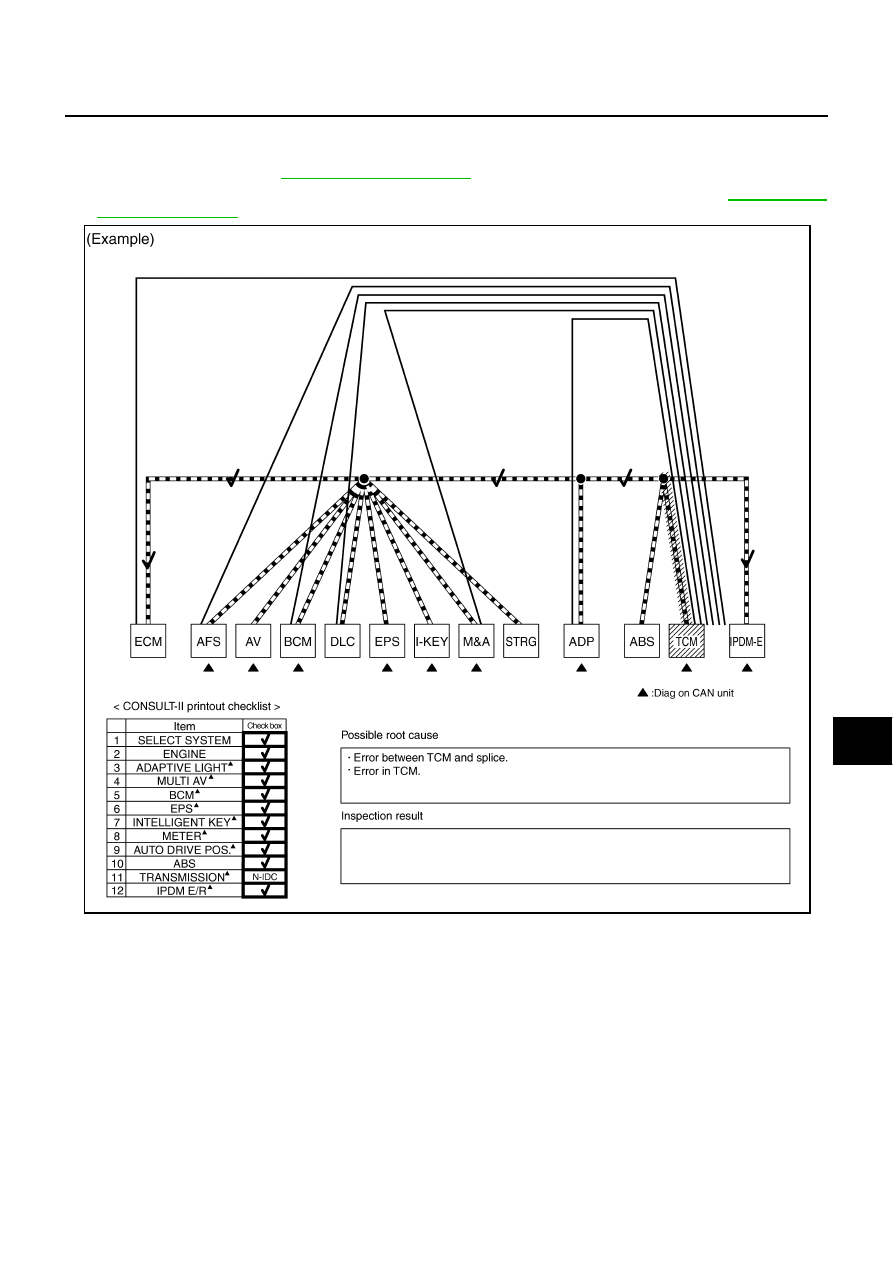
4.
Through the above procedure, the error is detected in the TCM branch line (shaded in the figure).
NOTE:
For abbreviations, refer to
5.
Perform the inspection for the detected error circuit. For the inspection procedure, refer to
SKIB8893E
LAN-32
[CAN FUNDAMENTAL]
TROUBLE DIAGNOSES WORK FLOW
Present Error — Short Circuit —
When the symptoms listed below exist, a short circuit of the CAN communication line is a possible cause.
Received data
Error symptom
●
Most the units connected to the CAN communication system go into fail-safe mode or are deactivated.
Inspection procedure
●
Refer to
LAN-82, "Malfunction Area Chart"
.
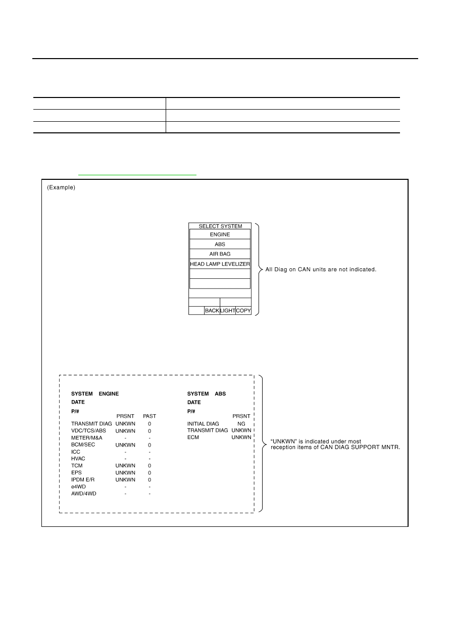
Item (CONSULT-II)
Indication
SELECT SYSTEM
All Diag on CAN units are not indicated.
CAN DIAG SUPPORT MNTR
“UNKWN” is indicated under “TRANSMIT DIAG” and most reception items.
SKIB8894E
Нет комментариевНе стесняйтесь поделиться с нами вашим ценным мнением.
Текст