Infiniti M35/M45 Y50. Manual — part 838
LAN-1
LAN SYSTEM
K ELECTRICAL
CONTENTS
C
D
E
F
G
H
I
J
L
M
SECTION
LAN
A
B
LAN
LAN SYSTEM
CAN FUNDAMENTAL
PRECAUTIONS . . . . . . . . . . . . . . .. 3
SYSTEM DESCRIPTION . . . . . . . . . . . 4
CAN Communication System . . . . . . . . ... 4
SYSTEM DIAGRAM . . . . . . . . . . . .. 4
CAN COMMUNICATION CONTROL CIRCUIT . . 5
Diag on CAN . . . . . . . . . . . . . . . 6
DESCRIPTION . . . . . . . . . . . . . .. 6
SYSTEM DIAGRAM . . . . . . . . . . . .. 6
TROUBLE DIAGNOSIS . . . . . . . . . . . .. 7
Condition of Error Detection . . . . . . . . . . 7
Symptom When Error Occurs in CAN Communi-
cation System . . . . . . . . . . . . . . ... 8
ERROR EXAMPLE . . . . . . . . . . . ... 8
Self-Diagnosis . . . . . . . . . . . . . . 12
CAN Diagnostic Support Monitor . . . . . . ... 13
MONITOR ITEM (CONSULT-II) . . . . . . .. 13
MONITOR ITEM (ON-BOARD DIAGNOSIS) . .. 14
TROUBLE DIAGNOSES WORK FLOW . . . . .. 15
CAN
INDEX FOR DTC . . . . . . . . . . . . . ... 40
DTC No. Index . . . . . . . . . . . . . . 40
HOW TO USE THIS SECTION . . . . . . . . . 41
Caution . . . . . . . . . . . . . . . . ... 41
Abbreviation List . . . . . . . . . . . . . . 41
PRECAUTIONS . . . . . . . . . . . . . . 42
TROUBLE DIAGNOSIS . . . . . . . . . . . 44
CAN Diagnostic Support Monitor . . . . . . . 44
MONITOR ITEM LIST (CONSULT-II) . . . . .. 44
CAN System Specification Chart . . . . . . . 50
VEHICLE EQUIPMENT IDENTIFICATION
INFORMATION . . . . . . . . . . . . . 51
CAN Communication Signal Chart . . . . . . . 52
CONSULT-II DATA ATTACHMENT SHEET . . 65
CAN System (Type 1) . . . . . . . . . . . . 70
DIAGNOSIS SHEET . . . . . . . . . . ... 70
CAN System (Type 2) . . . . . . . . . . . . 71
DIAGNOSIS SHEET . . . . . . . . . . ... 71
CAN System (Type 3) . . . . . . . . . . . . 72
DIAGNOSIS SHEET . . . . . . . . . . ... 72
CAN System (Type 4) . . . . . . . . . . . . 73
DIAGNOSIS SHEET . . . . . . . . . . ... 73
CAN System (Type 5) . . . . . . . . . . . . 74
DIAGNOSIS SHEET . . . . . . . . . . ... 74
LAN-2
CAN System (Type 7) . . . . . . . . . . . . 76
DIAGNOSIS SHEET . . . . . . . . . . . 76
CAN System (Type 8) . . . . . . . . . . . . 77
DIAGNOSIS SHEET . . . . . . . . . . . 77
CAN System (Type 9) . . . . . . . . . . . . 78
DIAGNOSIS SHEET . . . . . . . . . . . 78
CAN System (Type 10) . . . . . . . . . . ... 79
DIAGNOSIS SHEET . . . . . . . . . . . 79
CAN System (Type 11) . . . . . . . . . . ... 80
PRECAUTIONS
LAN-3
[CAN FUNDAMENTAL]
C
D
E
F
G
H
I
J
L
M
A
B
LAN
[CAN FUNDAMENTAL]
PRECAUTIONS
PFP:00001
Precautions When Using CONSULT-II
NKS004H7
Use CONSULT-II CONVERTER when connecting CONSULT-II to data link connector.
CAUTION:
CAN communication does not function properly if CONSULT-II is used without connecting CONSULT-II
CONVERTER.
Precautions for Trouble Diagnosis
NKS004H8
CAUTION:
●
Never apply 7.0 V or more to the measurement terminal.
●
Use a tester with open terminal voltage of 7.0 V or less.
●
Turn the ignition switch OFF and disconnect the battery cable from the negative terminal when
checking the harness.
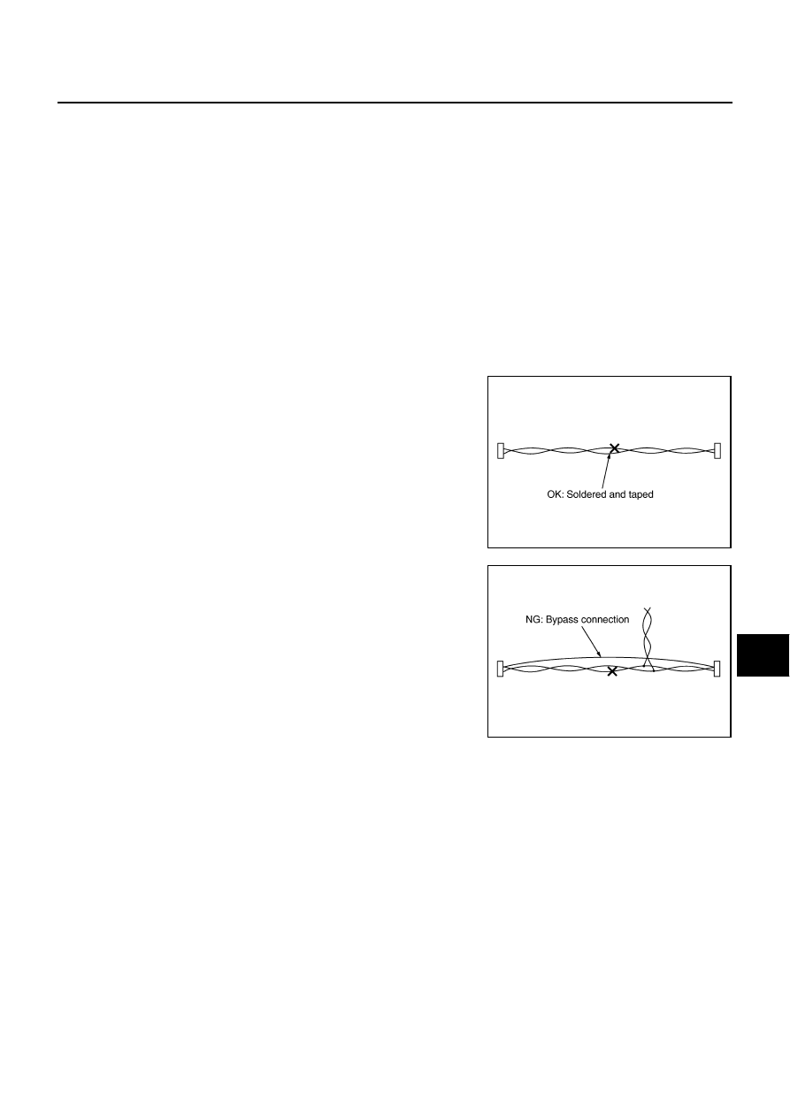
Precautions for Harness Repair
NKS004H9
●
Solder the repaired area and wrap tape around the soldered
area.
NOTE:
A fray of twisted lines must be within 110 mm (4.33 in).
●
Bypass connection is never allowed at the repaired area.
NOTE:
Bypass connection may cause CAN communication error. The
spliced wire becomes separated and the characteristics of
twisted line are lost.
●
Replace the applicable harness as an assembly if error is detected on the shield lines of CAN communi-
cation line.
SKIB8766E
SKIB8767E
LAN-4
[CAN FUNDAMENTAL]
SYSTEM DESCRIPTION
SYSTEM DESCRIPTION
PFP:00000
CAN Communication System
NKS004HA
●
CAN communication is a multiplex communication system. This enables the system to transmit and
receive large quantities of data at high speed by connecting control units with two communication lines
(CAN-H and CAN-L).
●
Control units on the CAN network transmit signals using the CAN communication control circuit. They
receive only necessary signals from other control units to operate various functions.
●
CAN communication lines adopt twisted-pair line style (two lines twisted) for noise immunity.
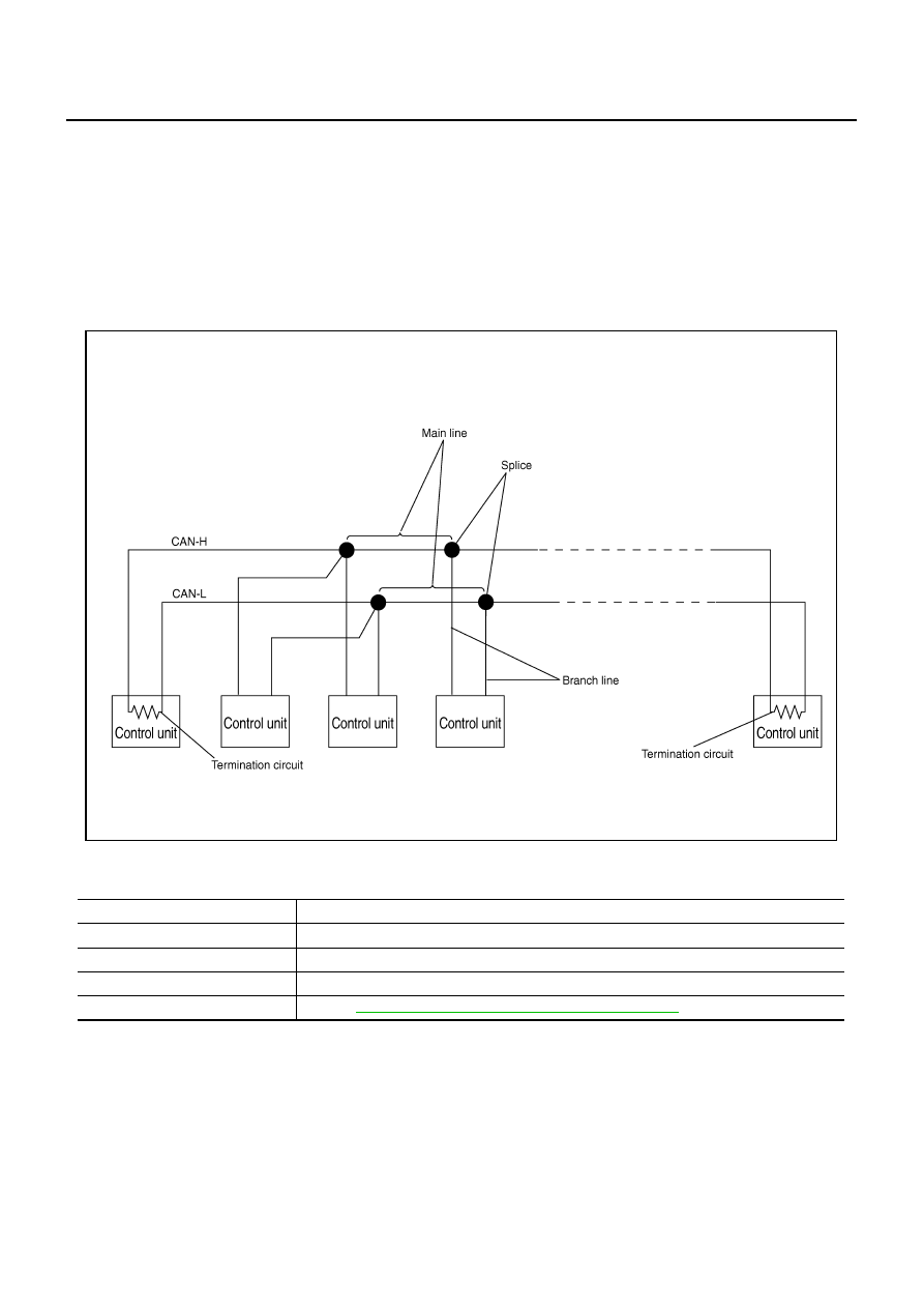
SYSTEM DIAGRAM
Each control unit passes an electric current to the termination circuits when transmitting CAN communication
signal. The termination circuits produce an electrical potential difference between CAN-H and CAN-L. CAN
communication system transmits and receives CAN communication signals by the potential difference.
SKIB8887E
Component
Description
Main line
CAN communication line between splices
Branch line
CAN communication line between splice and a control unit
Splice
A point connecting a branch line with a main line
Termination circuit
Refer to
Нет комментариевНе стесняйтесь поделиться с нами вашим ценным мнением.
Текст