Infiniti M35/M45 Y50. Manual — part 784
TRANSVERSE LINK
FSU-33
[AWD]
C
D
F
G
H
I
J
K
L
M
A
B
FSU
INSTALLATION
●
Installation is the reverse order of removal. For tightening torque, refer to
.
●
Perform final tightening of bolts and nuts at the front suspension member installation position and the
shock absorber lower side (rubber bushing) under unladen conditions with tires on level ground. Check
wheel alignment. Refer to
FSU-24, "Wheel Alignment Inspection"
.
●
Adjust neutral position of steering angle sensor after checking wheel alignment. Refer to
FSU-34
[AWD]
UPPER LINK
UPPER LINK
PFP:54524
Removal and Installation
NES000IX
REMOVAL
1.
Remove tires from vehicle with a power tool.
2.
Remove shock absorber. Refer to
FSU-29, "COIL SPRING AND SHOCK ABSORBER"
.
3.
Remove mounting nut and bolt with a power tool, and then remove upper link from steering knuckle.
4.
Remove mounting nuts and bolts, and then remove upper link and stopper rubber from vehicle.
INSPECTION AFTER REMOVAL
Visual Inspection
Check the following:
●
Upper link and bushing for deformation, cracks or damage. Replace it if a malfunction is detected.
●
Ball joint boot for cracks or other damage, and also for grease leakage. Replace it if a malfunction is
detected.
Ball Joint Inspection
Manually move ball stud to confirm it moves smoothly with no binding.
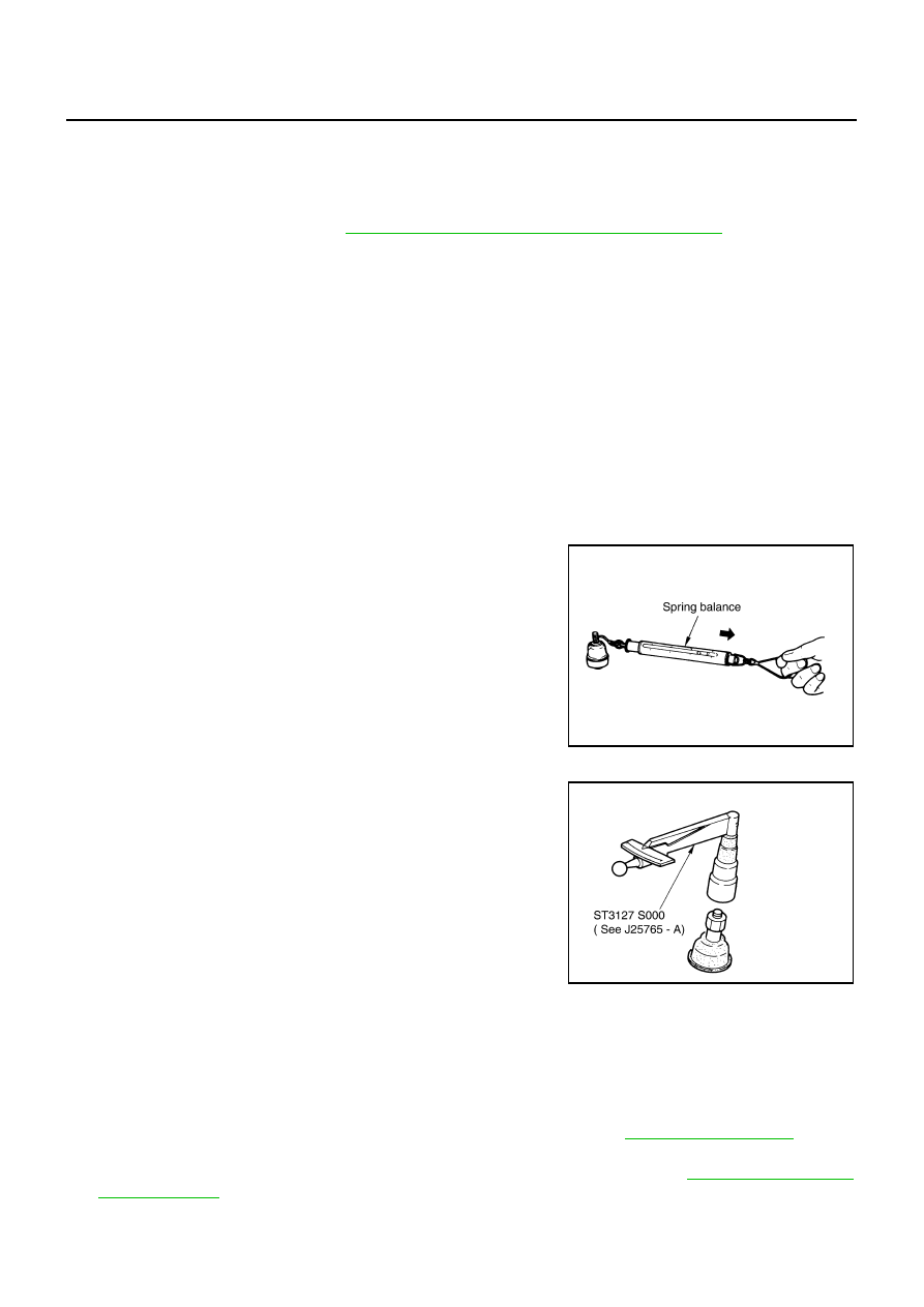
Swing Torque Inspection
NOTE:
Before measurement, move ball stud at least ten times by hand to check for smooth movement.
●
Hook a spring balance at cutout on ball stud. Confirm spring bal-
ance measurement value is within specifications when ball stud
begins moving.
●
If it is outside the specified range, replace upper link assembly.
Rotating Torque Inspection
●
Attach mounting nut to ball stud. Make sure that rotating torque
is within specifications with a preload gauge [SST].
●
If it is outside the specified range, replace upper link assembly.
Axial End Play Inspection
●
Move tip of ball stud in axial direction to check for looseness.
●
If it is outside the specified range, replace upper link assembly.
INSTALLATION
●
Installation is the reverse order of removal. For tightening torque, refer to
●
Perform final tightening of bolts and nuts at the vehicle installation position (rubber bushing) under
unladen conditions with tires on level ground. Check wheel alignment. Refer to
Swing torque
: 0 - 2.0 N·m (0 - 0.2 kg-m, 0 - 17 in-lb)
Spring balance measurement
: 0 - 61.5 N (0 - 6.2 kg, 0 - 13.6 lb)
SEIA0523E
Rotating torque
: 0 - 2.0 N·m (0 - 0.2 kg-m, 0 - 17 in-lb)
SDIA1150E
Axial end play
: 0 mm (0 in)
UPPER LINK
FSU-35
[AWD]
C
D
F
G
H
I
J
K
L
M
A
B
FSU
●
Adjust neutral position of steering angle sensor after checking wheel alignment. Refer to
FSU-36
[AWD]
STABILIZER BAR
STABILIZER BAR
PFP:54611
Removal and Installation
NES000IY
REMOVAL
1.
Remove tires from vehicle with a power tool.
2.
Remove undercover with a power tool.
3.
Remove the mounting nut on the lower side of stabilizer connecting rod with a power tool, and then
remove stabilizer connecting rod from stabilizer bar.
4.
If necessary remove the mounting nut on the upper side of stabilizer connecting rod with a power tool, and
then remove stabilizer connecting rod from transverse link.
5.
Remove the mounting nuts of stabilizer clamp, and then remove stabilizer clamp and stabilizer bushing.
6.
Remove stabilizer bar from vehicle.
INSPECTION AFTER REMOVAL
Check stabilizer bar, stabilizer connecting rod, stabilizer bushing, and stabilizer clamp for deformation, cracks
or damage. Replace it if a malfunction is detected.
INSTALLATION
Installation is the reverse order of removal. For tightening torque, refer to
Нет комментариевНе стесняйтесь поделиться с нами вашим ценным мнением.
Текст