Infiniti M35/M45 Y50. Manual — part 76
SHIFT CONTROL SYSTEM
AT-227
D
E
F
G
H
I
J
K
L
M
A
B
AT
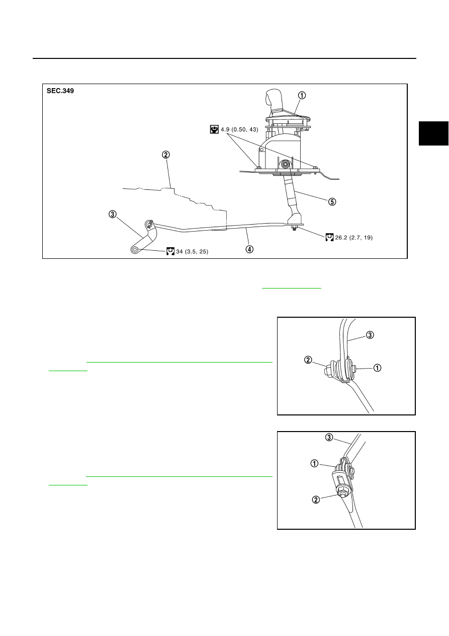
CONTROL ROD COMPONENTS (AWD MODELS)
Refer to the figure below for control rod removal and installation procedure.
Adjustment of A/T Position
NCS001QN
2WD MODELS
1.
Loosen nut (2) of pivot pin (1).
2.
Place PNP switch and selector lever in “P” position.
3.
While pressing lower lever (3) toward rear of vehicle (in “P” posi-
tion direction), tighten nut (2) to specified torque.
Refer to
AT-226, "CONTROL ROD COMPONENTS (2WD
.
AWD MODELS
1.
Loosen nut (2) of bracket (1).
2.
Place PNP switch and selector lever in “P” position.
3.
While pressing lower lever (3) toward rear of vehicle (in “P” posi-
tion direction), tighten nut (2) to specified torque.
Refer to
AT-227, "CONTROL ROD COMPONENTS (AWD
.
1.
Control device assembly
2.
A/T assembly
3.
Manual lever
4.
Control rod
5.
Lower lever
Refer to GI section to make sure icons (symbol marks) in the figure. Refer to
.
SCIA7055E
SCIA6354J
SCIA6353J
AT-228
SHIFT CONTROL SYSTEM
Checking of A/T Position
NCS001QO
1.
Place selector lever in “P” position, and turn ignition switch ON (engine stop).
2.
Make sure that selector lever can be shifted to other than “P” position when brake pedal is depressed.
Also make sure that selector lever can be shifted from “P” position only when brake pedal is depressed.
3.
Move the selector lever and check for excessive effort, sticking, noise or rattle.
4.
Confirm the selector lever stops at each position with the feel of engagement when it is moved through all
the positions. Check whether or not the actual position the selector lever is in matches the position shown
by the shift position indicator and the A/T body.
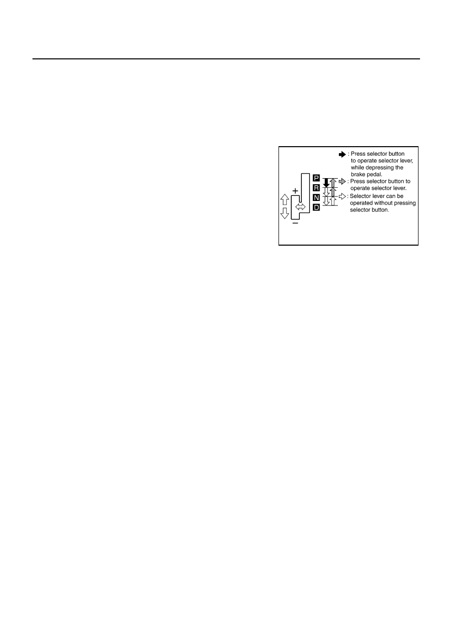
5.
The method of operating the lever to individual positions cor-
rectly should be as shown in the figure.
6.
When selector button is pressed in “P”, “R”, or “N” position with-
out applying forward/backward force to selector lever, check but-
ton operation for sticking.
7.
Confirm the back-up lamps illuminate only when lever is placed
in the “R” position. Confirm the back-up lamps does not illumi-
nate when selector lever is pushed against “R” position in the
“P” or “N” position.
8.
Confirm the engine can only be started with the selector lever in
the “P” and “N” positions. (With selector lever in the “P” position,
engine can be started even when selector lever is moved for-
ward and backward.)
9.
Make sure that A/T is locked completely in “P” position.
10. When selector lever is set to manual shift gate, make sure that manual mode is displayed on combination
meter.
Shift selector lever to “+” and “-” sides, and check that set shift position changes.
SCIA6760E
A/T SHIFT LOCK SYSTEM
AT-229
D
E
F
G
H
I
J
K
L
M
A
B
AT
A/T SHIFT LOCK SYSTEM
PFP:34950
Description
NCS001QP
The mechanical key interlock mechanism also operates as a shift lock:
With the ignition switch turned to ON, the selector lever cannot be shifted from “P” position to any other posi-
tions unless the brake pedal is depressed.
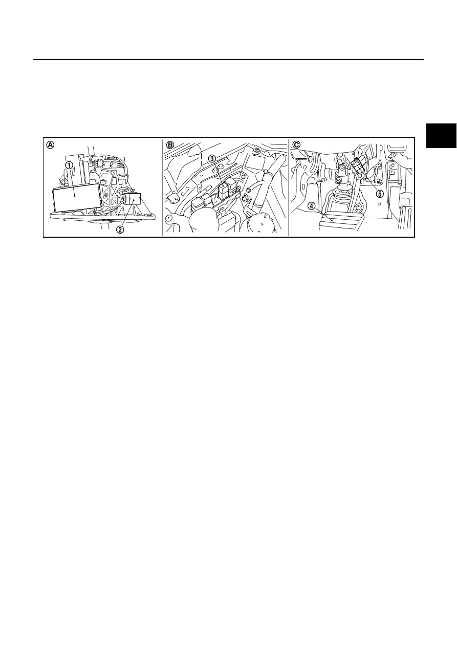
Shift Lock System Electrical Parts Location
NCS001QQ
A.
Control device assembly
B.
Engine room, right side
C.
Brake pedal, upper
1.
Shift lock unit (Shift lock solenoid installed)
2.
A/T device harness connector
3.
Shift lock relay
4.
Brake pedal
5.
Stop lamp switch
SCIA6743E
AT-230
A/T SHIFT LOCK SYSTEM
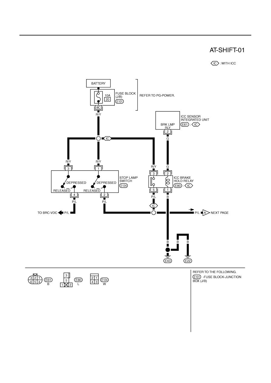
Wiring Diagram — AT — SHIFT
NCS001QR
TCWT0353E
Нет комментариевНе стесняйтесь поделиться с нами вашим ценным мнением.
Текст