Infiniti M35/M45 Y50. Manual — part 1150
FRONT WIPER AND WASHER SYSTEM
WW-5
C
D
E
F
G
H
I
J
L
M
A
B
WW
●
to CPU (central processing unit) located in IPDM E/R,
●
through 15 A fuse (No. 71, located in IPDM E/R)
●
to CPU located in IPDM E/R.
With the ignition switch in the ON or START position, power is supplied
●
to ignition relay, located in IPDM E/R,
●
through 15 A fuse [No. 1, located in fuse block (J/B)]
●
to BCM terminal 38,
●
through 10 A fuse [No. 12, located in fuse block (J/B)]
●
to front wiper reverse relay terminal 1,
●
through 10 A fuse (No. 84, located in IPDM E/R)
●
to front washer pump terminal 1
●
to front wiper motor terminal 4.
Ground is supplied
●
to BCM terminal 52
●
through grounds M16 and M70,
●
to IPDM E/R terminals 38 and 51
●
through grounds E22 and E43,
●
to combination switch terminal 12
●
through grounds M16 and M70.
LOW SPEED WIPER OPERATION
When wiper switch is in the LO position, BCM detects low speed wiper ON signal by BCM wiper switch read-
ing function.
BCM sends front wiper request signal (LO) with CAN communication line
●
from BCM terminals 39 and 40
●
to IPDM E/R terminals 49 and 50.
When IPDM E/R receives front wiper request signal (LO), it turns ON front wiper low relay, located in IPDM
E/R, power is supplied
●
through IPDM E/R terminal 23 and front wiper high relay and front wiper low relay
●
to front wiper motor terminal 3.
Ground is supplied
●
to front wiper motor terminal 1
●
through front wiper reverse relay terminals 3 and 4
●
through grounds E22 and E43.
With power and ground supplied, the front wiper motor operates at low speed.

WW-6
FRONT WIPER AND WASHER SYSTEM
HIGH SPEED WIPER OPERATION
When wiper switch is in the HI position, BCM detects high speed wiper ON signal by BCM wiper switch read-
ing function.
BCM sends front wiper request signal (HI) with CAN communication line
●
from BCM terminals 39 and 40
●
to IPDM E/R terminals 49 and 50.
When IPDM E/R receives front wiper request signal (HI), it turns ON front wiper high relay (located in IPDM
E/R) and front wiper reverse relay (located in relay box-1), power is supplied
●
through IPDM E/R terminal 19
●
through front wiper reverse relay terminals 5 and 3
●
to front wiper motor terminal 1.
Ground is supplied
●
to front wiper motor terminal 2
●
to IPDM E/R terminal 31 and front wiper high relay and front wiper low relay
●
to IPDM E/R terminal 38
●
through grounds E22 and E43.
With power and ground supplied, the front wiper motor operates at high speed.
INTERMITTENT OPERATION
1.
BCM detects ON/OFF status of intermittent operation dial position 1, 2 and 3 switched by wiper dial posi-
tion to judge wiper dial position status.
2.
BCM calculates intermittent operation interval time (second) from the vehicle speed signal received by
combination meter through CAN communication line and the wiper dial position.
Unit: second
NOTE:
The value in the table can differ from the actual vehicle speed.
3.
BCM switches front wiper request signal transmitted to IPDM E/R through CAN communication line from
STOP to LO once at intervals of intermittent operation time.
4.
IPDM E/R receives front wiper request signal (LO) once to turn ON front wiper main relay located in IPDM
E/R. Then operates front wiper. IPDM E/R receives front wiper auto stop signal (stop) input from front
wiper motor to turn OFF front wiper motor relay. IPDM E/R switches front wiper auto stop signal transmit-
ted through CAN communication line from MOVE to STOP.
5.
BCM receives front wiper auto stop signal (stop) to operate timer that determines intermittent operation
interval time till next front wiper motor operation.
Wiper dial position
Intermittent operation
interval time
Stopped
Vehicle speed; approx.
5 km/h (3.1 MPH) or
more to approx. 65 km/h
(40.4 MPH)
Vehicle speed approx.
65 km/h (40.4 MPH)
or more
1
Short
↑
↓
Long
1
0.4
0.2
2
2.5
1
0.6
3
5
2
1.2
4
7.5
3
1.8
5
12.5
5
3
6
25
10
6
7
40
16
9.6
FRONT WIPER AND WASHER SYSTEM
WW-7
C
D
E
F
G
H
I
J
L
M
A
B
WW
AUTO STOP OPERATION
With wiper switch turned OFF, wiper motor will continue to operate until wiper arms reach windshield base.
When wiper arms are not located at base of windshield with wiper switch OFF, ground is provided
●
from IPDM E/R terminal 23
●
to front wiper motor terminal 3, in order to continue wiper motor operation at low speed.
When wiper arms reach base of windshield, front wiper motor terminals 4 and 5 are connected
●
to IPDM E/R terminal 32
●
through front wiper motor terminals 4 and 5.
Then the IPDM E/R sends auto stop operation signal to BCM with CAN communication line.
When BCM receives auto stop operation signal, BCM sends wiper stop signal to IPDM E/R with CAN commu-
nication line.
IPDM E/R stops wiper motor. Wiper motor will then stop wiper arms at the STOP position.
WASHER OPERATION
When wiper switch is in front wiper washer position with ignition switch ON, BCM detects front wiper washer
signal by BCM wiper switch reading function (refer to
BCS-3, "COMBINATION SWITCH READING FUNC-
). Combination switch ground is supplied
●
to front washer pump terminal 2
●
through combination switch terminal 14
●
to combination switch terminal 12
●
through grounds M16 and M70.
With power and ground supplied, front washer pump is operated.
When BCM detects that front washer pump has operated for 0.4 seconds or longer, BCM operates front wiper
motor for low speed.
When BCM detects washer switch is OFF, low speed operation cycles approximately 2 times and stops.
MIST OPERATION
When the wiper switch is turned to the MIST position, wiper low speed operation cycles once and then stops.
For additional information about wiper operation under this condition, refer to
If the switch is held in the MIST position, low speed operation continues.
FAIL-SAFE FUNCTION
If an abnormality occurs in CAN communications, IPDM E/R holds the condition just before fail-safe status is
initiated until ignition switch is turned OFF. (If wipers were operating in LO just before the initiation of fail-safe
status, they continue to operate in LOW until ignition switch is turned OFF.)
WW-8
FRONT WIPER AND WASHER SYSTEM
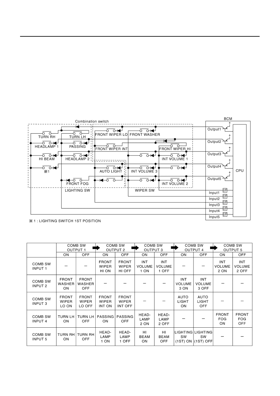
COMBINATION SWITCH READING FUNCTION
Description
●
BCM reads combination switch (wiper) status, and controls front wipers according to the results.
●
BCM reads information of a maximum of 20 switches by combining five output terminals (OUTPUT 1-5)
and five input terminals (INPUT 1-5).
Operation Description
●
BCM activates transistors of output terminals (OUTPUT 1-5) periodically and allows current to flow in turn.
●
If any (one or more) switches are turned ON, circuit of output terminals (OUTPUT 1-5) and input terminals
(INPUT 1-5) becomes active.
●
At this time, transistors of output terminals (OUTPUT 1-5) are activated to allow current to flow. When volt-
age of input terminals (INPUT 1-5) corresponding to that switch changes, interface in BCM detects volt-
age change, and BCM determines that the switch is ON.
BCM - Operation Table of Combination Switches
●
BCM reads operation status of combination switch using combinations shown in table below.
PKID0470E
PKIC0276E
Нет комментариевНе стесняйтесь поделиться с нами вашим ценным мнением.
Текст