Infiniti M35/M45 Y50. Manual — part 435
DTC P0112, P0113 IAT SENSOR
EC-213
[VQ35DE]
C
D
E
F
G
H
I
J
K
L
M
A
EC
3.
CHECK INTAKE AIR TEMPERATURE SENSOR GROUND CIRCUIT FOR OPEN AND SHORT
1.
Turn ignition switch OFF.
2.
Disconnect ECM harness connector.
3.
Check harness continuity between mass air flow sensor terminal 6 and ECM terminal 67.
Refer to Wiring Diagram.
4.
Also check harness for short to ground and short to power.
OK or NG
OK
>> GO TO 4.
NG
>> Repair open circuit or short to ground or short to power in harness or connectors.
4.
CHECK INTAKE AIR TEMPERATURE SENSOR
Refer to
EC-213, "Component Inspection"
OK or NG
OK
>> GO TO 5.
NG
>> Replace mass air flow sensor (with intake air temperature sensor).
5.
CHECK INTERMITTENT INCIDENT
Refer to
EC-153, "TROUBLE DIAGNOSIS FOR INTERMITTENT INCIDENT"
>> INSPECTION END
Component Inspection
NBS004VA
INTAKE AIR TEMPERATURE SENSOR
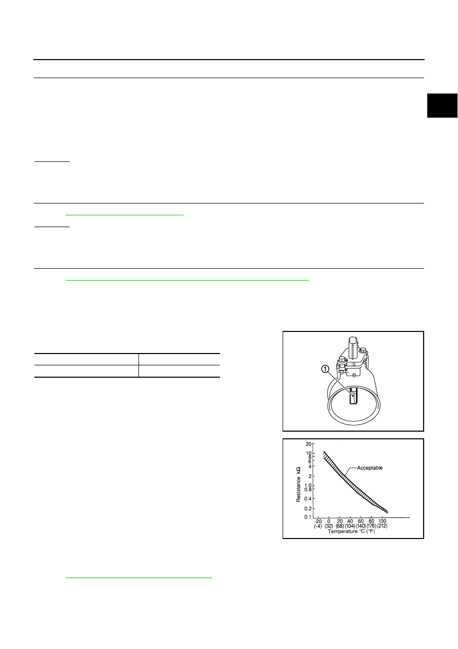
1.
Check resistance between mass air flow sensor (1) terminals 5
and 6 under the following conditions.
2.
If NG, replace mass air flow sensor (with intake air temperature
sensor).
Removal and Installation
NBS004VB
MASS AIR FLOW SENSOR
Refer to
EM-19, "AIR CLEANER AND AIR DUCT"
.
Continuity should exist.
Intake air temperature
°
C (
°
F)
Resistance k
Ω
25 (77)
1.800 - 2.200
PBIA9559J
SEF012P
EC-214
[VQ35DE]
DTC P0117, P0118 ECT SENSOR
DTC P0117, P0118 ECT SENSOR
PFP:22630
Component Description
NBS004VC
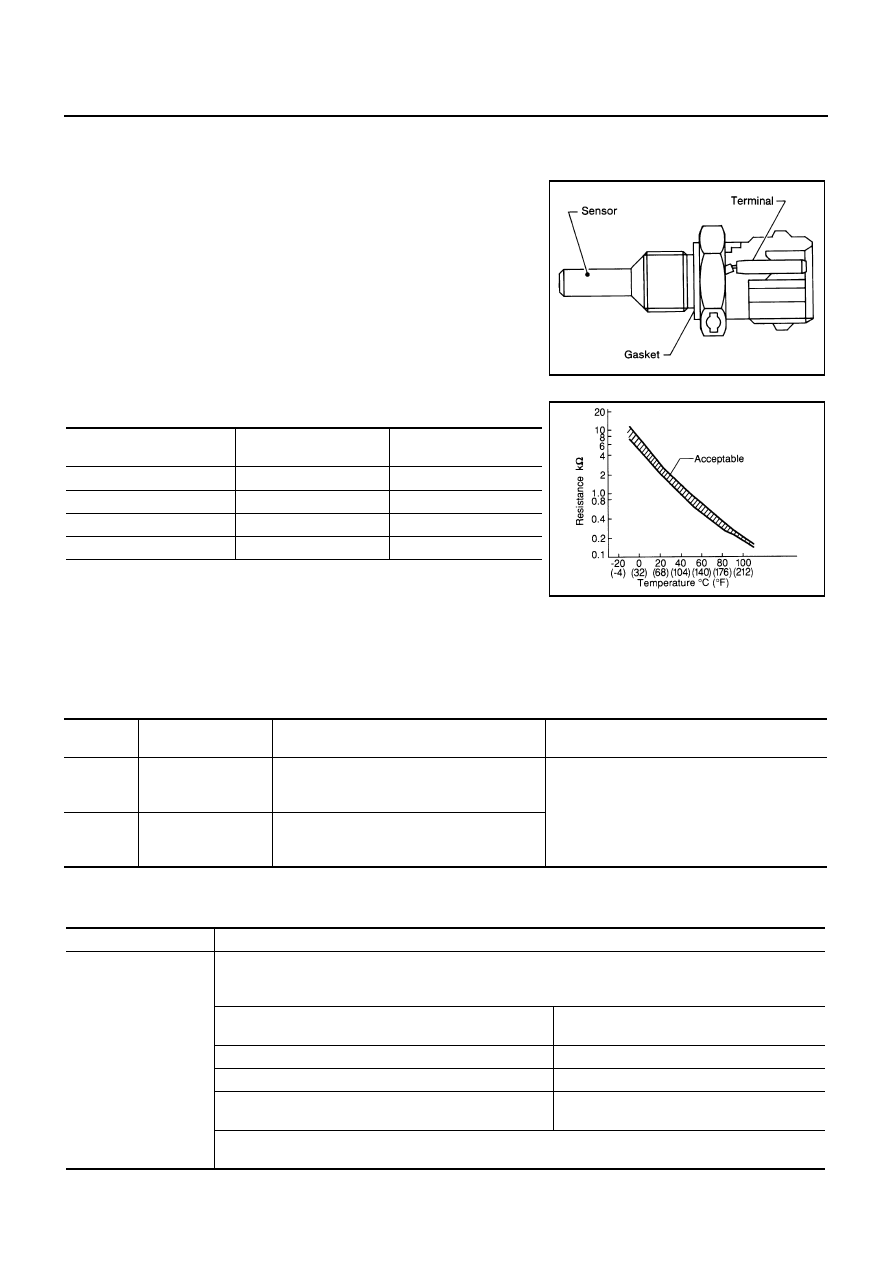
The engine coolant temperature sensor is used to detect the engine
coolant temperature. The sensor modifies a voltage signal from the
ECM. The modified signal returns to the ECM as the engine coolant
temperature input. The sensor uses a thermistor which is sensitive to
the change in temperature. The electrical resistance of the ther-
mistor decreases as temperature increases.
<Reference data>
*: This data is reference value and is measured between ECM terminal 73 (Engine
coolant temperature sensor) and ground.
CAUTION:
Do not use ECM ground terminals when measuring input/output voltage. Doing so may result in dam-
age to the ECM's transistor. Use a ground other than ECM terminals, such as the ground.
On Board Diagnosis Logic
NBS004VD
These self-diagnoses have the one trip detection logic.
FAIL-SAFE MODE
When the malfunction is detected, the ECM enters fail-safe mode and the MIL lights up.
SEF594K
Engine coolant temperature
°
C (
°
F)
Voltage*
V
Resistance
k
Ω
–10 (14)
4.4
7.0 - 11.4
20 (68)
3.5
2.1 - 2.9
50 (122)
2.2
0.68 - 1.00
90 (194)
0.9
0.236 - 0.260
SEF012P
DTC No.
Trouble Diagnosis
Name
DTC Detecting Condition
Possible Cause
P0117
0117
Engine coolant tem-
perature sensor cir-
cuit low input
An excessively low voltage from the sensor is
sent to ECM.
●
Harness or connectors
(The sensor circuit is open or shorted.)
●
Engine coolant temperature sensor
P0118
0118
Engine coolant tem-
perature sensor cir-
cuit high input
An excessively high voltage from the sensor is
sent to ECM.
Detected items
Engine operating condition in fail-safe mode
Engine coolant temper-
ature sensor circuit
Engine coolant temperature will be determined by ECM based on the time after turning ignition switch ON
or START.
CONSULT-II displays the engine coolant temperature decided by ECM.
Condition
Engine coolant temperature decided
(CONSULT-II display)
Just as ignition switch is turned ON or START
40
°
C (104
°
F)
More than approx. 4 minutes after ignition ON or START
80
°
C (176
°
F)
Except as shown above
40 - 80
°
C (104 - 176
°
F)
(Depends on the time)
When the fail-safe system for engine coolant temperature sensor is activated, the cooling fan operates
while engine is running.
DTC P0117, P0118 ECT SENSOR
EC-215
[VQ35DE]
C
D
E
F
G
H
I
J
K
L
M
A
EC
DTC Confirmation Procedure
NBS004VE
NOTE:
If DTC Confirmation Procedure has been previously conducted, always turn ignition switch OFF and wait at
least 10 seconds before conducting the next test.
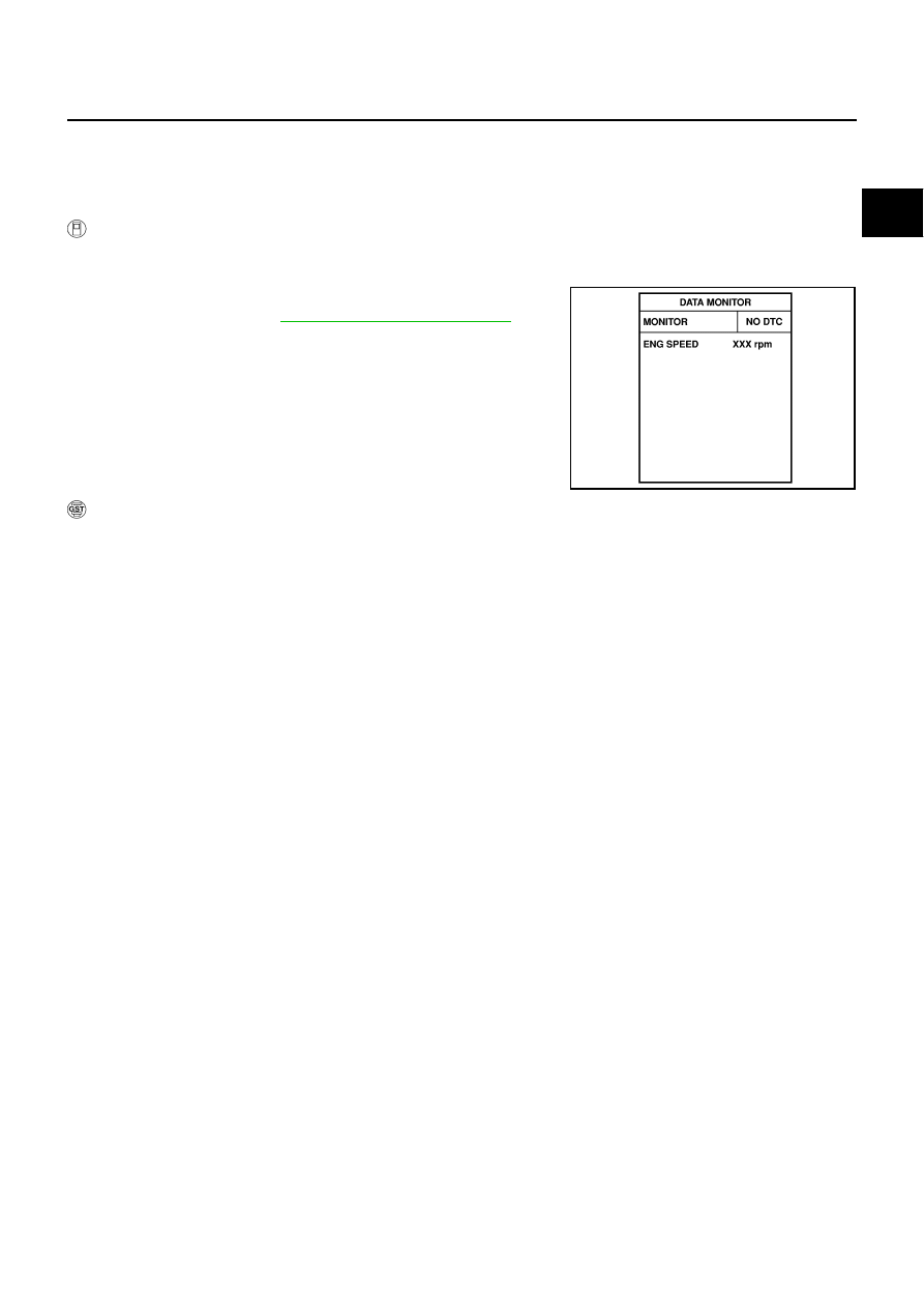
WITH CONSULT-II
1.
Turn ignition switch ON.
2.
Select “DATA MONITOR” mode with CONSULT-II.
3.
Wait at least 5 seconds.
4.
EC-217, "Diagnostic Procedure"
.
WITH GST
Follow the procedure “WITH CONSULT-II” above.
SEF058Y
EC-216
[VQ35DE]
DTC P0117, P0118 ECT SENSOR
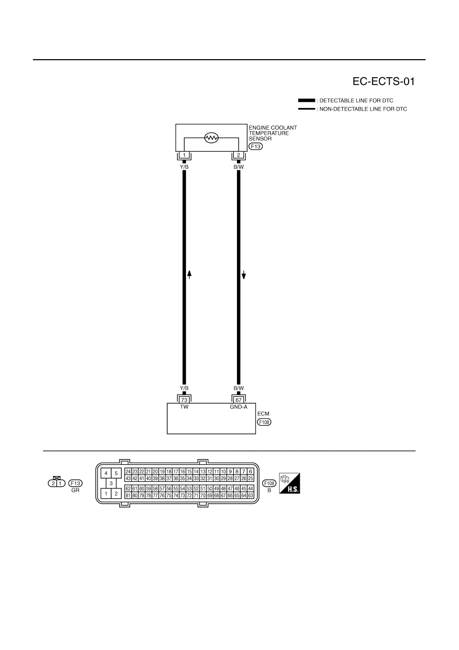
Wiring Diagram
NBS004VF
TBWT0952E
Нет комментариевНе стесняйтесь поделиться с нами вашим ценным мнением.
Текст