Infiniti M35/M45 Y50. Manual — part 901
ACTIVE AFS
LT-149
C
D
E
F
G
H
I
J
L
M
A
B
LT
Terminals and Reference Values for AFS Control Unit
NKS003QJ
Ter-
minal
No.
Wire
color
Item
Measuring condition
Reference value
Ignition
switch
Operation or condition
1
B/R
IGN power supply
ON
—
Battery voltage
2
W/R
Swivel position sensor ground
(right)
ON
—
Approx. 0 V
3
GR
AFS switch signal
ON
AFS switch
ON
Approx. 0 V
OFF
Battery voltage
4
Y
Swivel position sensor power
supply (right)
ON
—
Approx. 5 V
6
V/W
Height sensor power supply
ON
—
Approx. 5 V
7
P
CAN-L
—
—
—
8
B/R
Height sensor ground
ON
—
Approx. 0 V
9
W/B
Swivel position sensor signal
(right)
ON
Low beam headlamp
(right) swivel angle
0
°
Approx. 1.5 V
Maximum
angle
Approx. 2.5 V
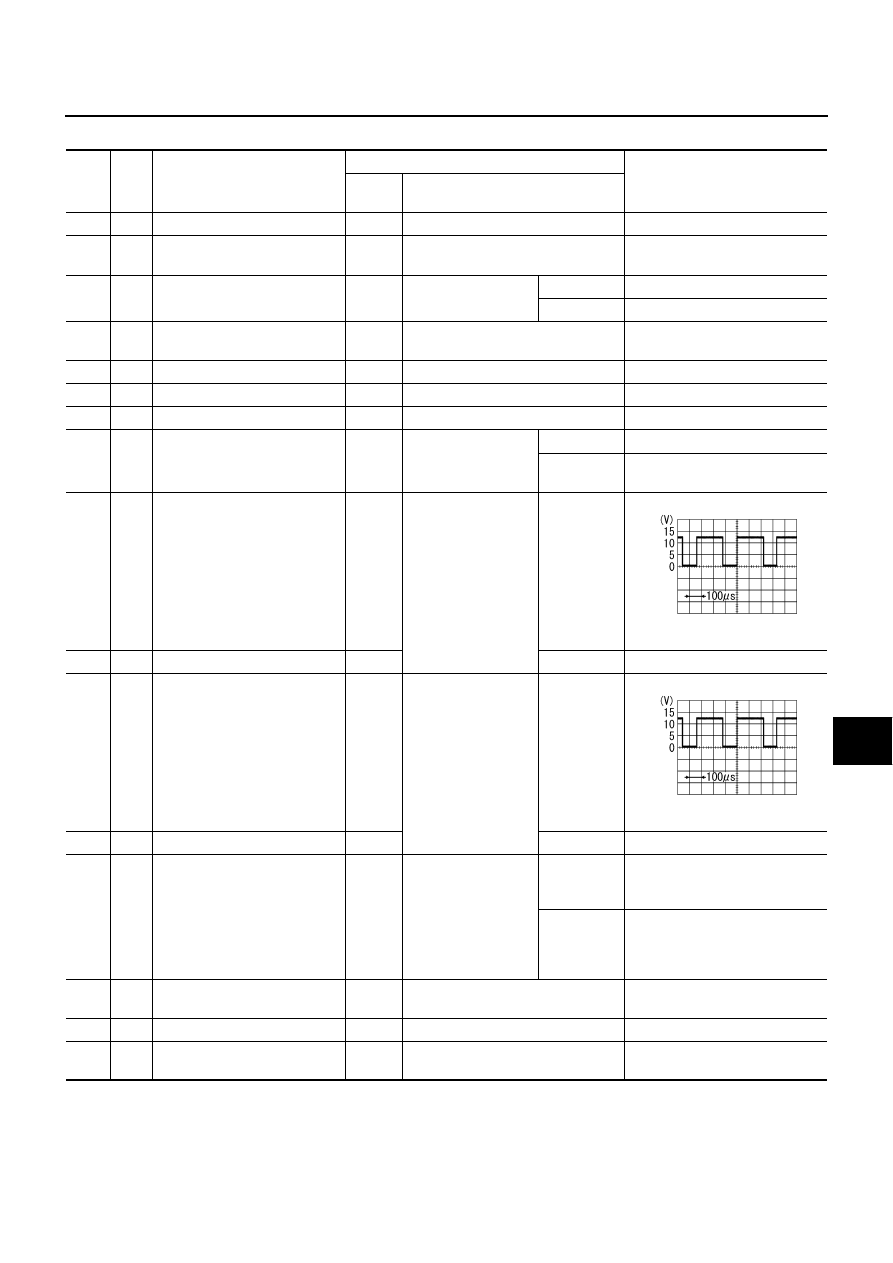
11
R
Swivel motor 1 phase
−
(right)
ON
Low beam headlamp
(right) swivel
ON
Reference waveform
Approx. 8 - 12 V
13
B
Swivel motor 2 phase
−
(right)
ON
OFF
Approx. 9.5 - 11.5 V
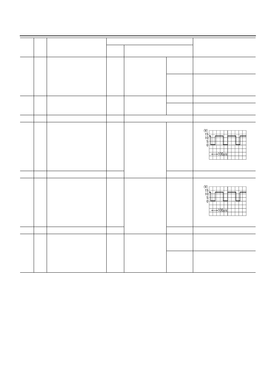
15
BR/L
Swivel motor 1 phase+ (left)
ON
Low beam headlamp
(left) swivel
ON
Reference waveform
Approx. 8 - 12 V
17
Y/G
Swivel motor 2 phase+ (left)
ON
OFF
Approx. 9.5 - 11.5 V
19
V
Aiming motor drive signal (right)
ON
Low beam headlamp
(right) auto aiming
Unloaded
vehicle posi-
tion
Approx. 9 V
Maximum
laden condi-
tion
Approx. 4.8 V
(With 18- inch wheel)
Approx. 5.2 V
(With 19 -inch wheel)
24
V/R
Swivel position sensor power
supply (left)
ON
—
Approx. 5 V
25
B
Ground
ON
—
Approx. 0 V
27
R/W
Swivel position sensor ground
(left)
ON
—
Approx. 0 V
SKIB2408J
SKIB2408J
LT-150
ACTIVE AFS
28
BR
Height sensor signal
ON
Vehicle height
Unloaded
vehicle posi-
tion
Approx. 2.5 V
Maximum
laden condi-
tion
Approx. 1.0 V
(With 18- inch wheel)
Approx. 1.3 V
(With 19- inch wheel)
29
L/Y
Swivel position sensor signal
(left)
ON
Low beam headlamp
(left) swivel angle
0
°
Approx. 1.5 V
Maximum
angle
Approx. 3.5 V
30
L
CAN-H
—
—
—
32
W
Swivel motor 2 phase+ (right)
ON
Low beam headlamp
(right) swivel
ON
Reference waveform
Approx. 8 - 12 V
34
G
Swivel motor 1phase+ (right)
ON
OFF
Approx. 9.5 - 11.5V
36
Y/L
Swivel motor 2 phase
−
(left)
ON
Low beam headlamp
(left) swivel
ON
Reference waveform
Approx. 8 - 12 V
38
W/L
Swivel motor 1 phase
−
(left)
ON
OFF
Approx. 9.5 - 11.5 V
40
O
Aiming motor drive signal (left)
ON
Low beam headlamp
(left) auto aiming
Unloaded
vehicle posi-
tion
Approx. 9 V
Maximum
laden condi-
tion
Approx. 4.8 V
(With 18 -inch wheel)
Approx. 5.2 V
(With 19 -inch wheel)
Ter-
minal
No.
Wire
color
Item
Measuring condition
Reference value
Ignition
switch
Operation or condition
SKIB2408J
SKIB2408J
ACTIVE AFS
LT-151
C
D
E
F
G
H
I
J
L
M
A
B
LT
How to Proceed with Trouble Diagnosis
NKS003QK
1.
Confirm the symptom or customer complaint.
2.
Understand operation description and function description. Refer to
.
3.
Perform the preliminary check. Refer to
4.
Perform self-diagnosis by CONSULT-II. Refer to
5.
Check symptom and repair or replace the cause of malfunction.
6.
Does the AFS operate normally? If YES: GO TO 7. If NO: GO TO 4.
7.
INSPECTION END
Preliminary Check
NKS003QL
1.
CHECK FUSES AND FUSIBLE LINK
Check for blown fuses and fusible link.
Refer to
LT-143, "Wiring Diagram — AFS —"
OK or NG
OK
>> GO TO 2.
NG
>> If the fuse is brown be sure to eliminate cause of malfunction before installing new fuse. Refer to
PG-3, "POWER SUPPLY ROUTING CIRCUIT"
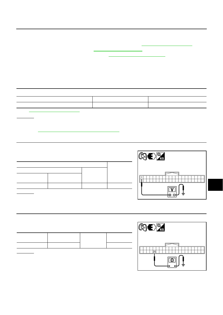
2.
CHECK AFS CONTROL UNIT VOLTAGE
1.
Turn ignition switch ON.
2.
Check voltage between AFS control unit harness connector and
ground.
OK or NG
OK
>> GO TO 3.
NG
>> Repair harness or connector.
3.
CHECK GROUND CIRCUIT
1.
Turn ignition switch OFF.
2.
Check continuity between AFS control unit harness connector
and ground.
OK or NG
OK
>> INSPECTION END
NG
>> Repair harness or connector.
Unit
Power source
Fuse No.
AFS control unit
Ignition switch ON or START
12
Terminals
Voltage
(Approx.)
(+)
(-)
AFS control unit
connector
Terminal
F110
1
Ground
Battery voltage
SKIB4776E
AFS control unit
connector
Terminal
Ground
Continuity
F110
25
Yes
SKIB4775E

LT-152
ACTIVE AFS
CONSULT-II Function (ADAPTIVE LIGHT)
NKS003QM
CONSULT-II can display each diagnostic item using diagnostic test modes shown following.
CONSULT-II BASIC OPERATION
Refer to
GI-38, "CONSULT-II Start Procedure"
WORK SUPPORT (STEERING ANGLE SENSOR ADJUSTMENT)
Work Support Item List
CAUTION:
Never use this function but on VDC side.
Notes on Steering Angle Sensor (Neutral Point) Adjustment
●
Be sure to adjust steering angle sensor neutral point before driving if any of the following has been
removed/installed or replaced: Steering angle sensor; Steering system part, Suspension system part.
●
On vehicle with VDC, perform steering angle sensor neutral point adjustment only on VDC side. Never
perform the adjustment on ADAPTIVE LIGHT side as this may lead to VDC malfunctions. If the adjust-
ment has been performed on AFS side, readjust on VDC side. For steering angle sensor neutral point
adjustment procedures on VDC side, refer to
BRC-6, "Adjustment of Steering Angle Sensor Neutral Posi-
in “ON-VEHICLE SERVICE”.
●
When replaced steering angle sensor, AFS control unit detects “DTC B2515 ST ANG SEN SIG”. Delete
the malfunction history after adjust steering angle sensor on VDC side.
●
Steering angle sensor neutral point adjustment should be performed using CONSULT-II. (The adjustment
will not be possible without CONSULT-II.)
Operation Procedure
Refer to
BRC-6, "Adjustment of Steering Angle Sensor Neutral Position"
.
WORK SUPPORT (LEVELIZER ADJUSTMENT)
Work Support Item List
Operation Procedure
1.
Set the vehicle in unload condition. (Removal all loads in driver, passenger and trunk rooms.)
2.
Touch “ADAPTIVE LIGHT” on “SELECT SYSTEM” screen.
3.
Touch “WORK SUPPORT” on “SELECT DIAG MODE” screen.
4.
Touch “LEVELIZER ADJUSTMENT”.
5.
Touch “START”.
6.
“ADJUSTMENT COMPLETE” will be displayed.
CAUTION:
When “CAN NOT BE TESTED” is displayed, AFS control unit stops levelizer adjustment as it
detected the change of height sensor signal. AFS control unit detects “DTC B2519 LEVELIZER
CALIB”.
System part
Check item, diagnosis mode
Description
ADAPTIVE LIGHT
WORK SUPPORT
Adjusts steering angle sensor (Never use this function but on VDC side) and
adjusts levelizer.
SELF-DIAG RESULTS
Displays self-diagnosis
DATA MONITOR
Displays AFS control unit inputs and outputs in real time.
CAN DIAG SUPPORT MNTR
The result of transmit/receive diagnosis of CAN communication can be read.
ACTIVE TEST
AFS control unit sends a drive signal to electronic components to check their
operation.
ECU PART NUMBER
AFS control unit part number can be read.
Item
Description
ST ANG SEN ADJUSTMENT
Adjust steering angle sensor neutral point (straight-ahead position).
Item
Description
LEVELIZER ADJUSTMENT
Adjust the height sensor signal value at unloaded vehicle position recognized by AFS control unit.
Нет комментариевНе стесняйтесь поделиться с нами вашим ценным мнением.
Текст