Infiniti M35/M45 Y50. Manual — part 182
DIAGNOSIS SYSTEM
AV-105
[WITHOUT MOBILE ENTERTAINMENT SYSTEM]
C
D
E
F
G
H
I
J
L
M
A
B
AV
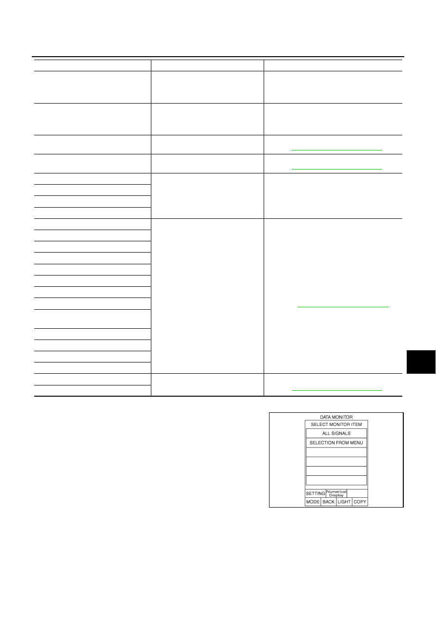
DATA MONITOR
When “DATA MONITOR” is selected, “ALL SIGNALS” and “SELEC-
TION FROM MENU” are displayed.
GPS ANTENNA CONN [U1244]
GPS antenna connection malfunction
is detected
●
GPS antenna feeder
●
GPS antenna
●
NAVI control unit
CAMERA CONT CONN [U1250]
Camera and connection recognition
signal circuit malfunction is detected
●
Camera-connection recognition signal circuit
●
Camera control unit
●
AV (NAVI) control unit
Cont Unit FLASH-ROM [U1200]
AV (NAVI) control unit malfunction is
detected
Replace AV (NAVI) control unit
Refer to
AV-131, "AV (NAVI) Control Unit"
GYRO NO CONN [U1201]
NAVI control unit malfunction is
detected
Replace NAVI control unit
Refer to
AV-131, "AV (NAVI) Control Unit"
GPS COMM [U1204]
GPS malfunction is detected
If the symptoms such as the GPS receipt mal-
function occur, intermittent malfunction caused
by strong radio interference may be detected.
If the malfunction always occurs, replace NAVI
control unit.
GPS ROM [U1205]
GPS RAM [U1206]
GPS RTC [U1207]
DVD-ROM COMM [U1208]
●
Malfunction is detected on DVD-
ROM drive pickup lens in NAVI con-
trol unit
●
There is dirt and damage on the map
disc
●
Map disc
●
NAVI control unit
Refer to
AV-131, "AV (NAVI) Control Unit"
DVD-ROM READ [U1209]
DVD-ROM DISC [U120A]
DVD-ROM MECHA DETECT [U120C]
DVD-ROM DRIVE MECHA [U120D]
DVD-ROM FOCUS [U120E]
DVD-ROM TOC [U120F]
DVD-ROM SEEK [U1210]
DVD-ROM ERR CORRECTION
[U1211]
DVD-ROM DATA FORWARD [U1212]
DVD-ROM DATA [U1213]
DVD-ROM TIMEOUT [U1214]
DVD-ROM LOAD [U1215]
CAN CONT [U1216]
AV (NAVI) control unit malfunction is
detected
Replace AV (NAVI) control unit
Refer to
AV-131, "AV (NAVI) Control Unit"
BLUETOOTH CONN [U1217]
Error item
Description
Possible cause/Action to take
SKIB3675E
AV-106
[WITHOUT MOBILE ENTERTAINMENT SYSTEM]
DIAGNOSIS SYSTEM
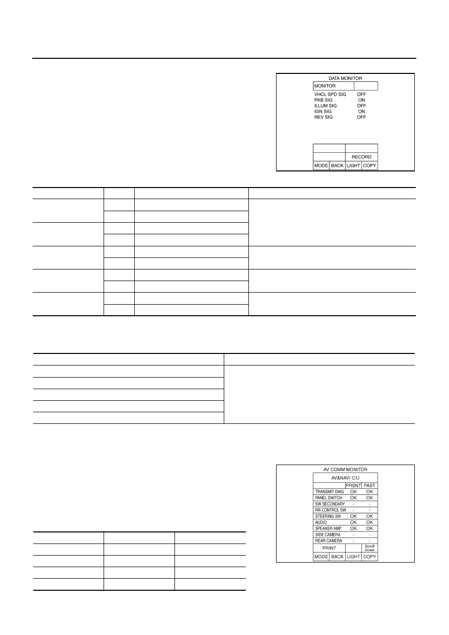
ALL SIGNALS
●
When “ALL SIGNALS” is selected and “START” is touched, the
following vehicle signal condition that is input to AV (NAVI) con-
trol unit is displayed.
●
For each signal, a comparison of actual operating status and the
status recognized by the system can be checked.
Display Condition
SELECTION FROM MENU
●
When “SELECTION FROM MENU” is selected, the vehicle signal display can be selected. After that, the
selected vehicle signal condition is displayed when “START” is touched.
AV COMM MONITOR
When “AV COMM MONITOR” is selected, “AV&NAVI C/U” and “AUDIO” are displayed.
AV&NAVI C/U
●
When “AV&NAVI C/U” is selected, the communication condition
from AV (NAVI) control unit to each unit and malfunction counter
are displayed.
●
Error counter displays OK if any malfunction is not detected in
the past. If the malfunction is detected, it displays 0. When turn-
ing the ignition switch ON, if it is normal, it displays 1. The upper
limit of the counter is 39.
SKIB3676E
Display Item
Display
Vehicle status
Remarks
VHCL SPD SIG
ON
Vehicle speed > 0 km/h (0 MPH)
Changes in indication may be delayed. This is normal.
OFF
Vehicle speed = 0 km/h (0 MPH)
PKB SIG
ON
Parking brake is applied.
OFF
Parking brake is released.
ILLMU SIG
ON
Light switch ON
–
OFF
Light switch OFF
IGN SIG
ON
Ignition switch ON
–
OFF
Ignition switch in ACC position
REV SIG
ON
Selector lever in R position
Changes in indication may be delayed. This is normal.
OFF
Other than selector lever in R position
Item to be selected
Description
VHCL SPD SIG
As well as selecting “ALL SIGNALS”
PKB SIG
ILLUM SIG
IGN SIG
REV SIG
Items
Display (PRSNT)
Error counter (PAST)
TRANSMIT DIAG
OK / UNKWN
OK / 0 - 39
PANEL SWITCH
OK / UNKWN
OK / 0 - 39
SW SECONDARY
-
-
RR CONTROL SW
-
-
SKIB3678E
DIAGNOSIS SYSTEM
AV-107
[WITHOUT MOBILE ENTERTAINMENT SYSTEM]
C
D
E
F
G
H
I
J
L
M
A
B
AV
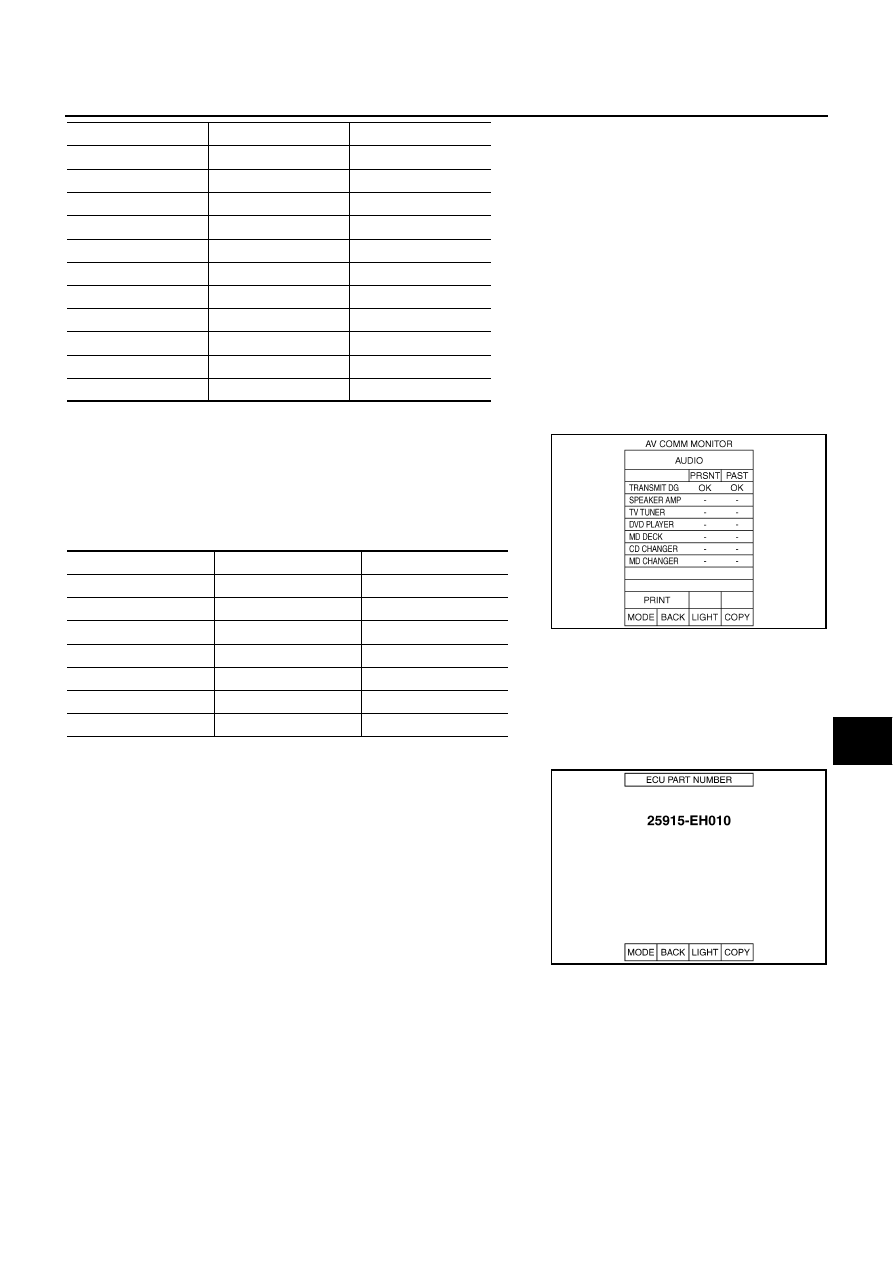
AUDIO
●
When “AUDIO” is selected, the communication condition from
audio unit to each unit and malfunction counter are displayed.
●
Error counter displays OK if any malfunction is not detected in
the past. If the malfunction is detected, it displays 0. When turn-
ing the ignition switch ON, if it is normal, it displays 1. The upper
limit of the counter is 39.
ECU PART NUMBER
The part number of AV (NAVI) control unit is displayed.
STEERING SW
OK / UNKWN
OK / 0 - 39
AUDIO
OK / UNKWN
OK / 0 - 39
SPEAKER AMP
OK / UNKWN
OK / 0 - 39
SIDE CAMERA
-
-
REAR CAMERA
OK / UNKWN
OK / 0 - 39
TV TUNER
-
-
DVD PLAYER
OK / UNKWN
OK / 0 - 39
VIDEO DIST
-
-
ETC
-
-
FM MULTI
-
-
REMOTE CONT
-
-
Items
Display (PRSNT)
Error counter (PAST)
Items
Display (Current)
Error counter (Past)
TRANSMIT DG
OK / UNKWN
OK / 0 - 39
SPEAKER AMP
OK / UNKWN
OK / 0 - 39
TV TUNER
-
-
DVD PLAYER
OK / UNKWN
OK / 0 - 39
MD DECK
-
-
CD CHANGER
-
-
MD CHANGER
-
-
SKIB3679E
SKIB3680E
AV-108
[WITHOUT MOBILE ENTERTAINMENT SYSTEM]
TROUBLE DIAGNOSIS
TROUBLE DIAGNOSIS
PFP:00004
Multifunction Switch Cannot Be Operated
NKS00490
1.
PERFORM CONSULT-II SELF-DIAGNOSIS
Perform CONSULT-II self-diagnosis and check the malfunction. Refer to
Is there a malfunction?
YES
>>
AV-103, "Display Item of SELF-DIAG RESULTS"
NO
>> Replace multifunction switch.
RGB Image Is Not Displayed
NKS00491
1.
DIAGNOSIS USING CONSULT-II
Start CONSULT-II, and make sure that “MULTI AV” is displayed on SELECT SYSTEM screen. Refer to
OK or NG
OK
>> GO TO 2.
NG
>> Check AV (NAVI) control unit power supply and ground circuit.
2.
PERFORM CONSULT-II SELF-DIAGNOSIS
Perform CONSULT-II self-diagnosis and check the malfunction. Refer to
Is there a malfunction?
YES
>> Refer to
AV-103, "Display Item of SELF-DIAG RESULTS"
NO
>> GO TO 3.
3.
CHECK HARNESS BETWEEN AV (NAVI) CONTROL UNIT AND FRONT DISPLAY UNIT
1.
Turn ignition switch OFF.
2.
Disconnect AV (NAVI) control unit connector and front display unit connector.
3.
Check continuity between AV (NAVI) control unit harness con-
nector M210 terminal 50 and ground.
OK or NG
OK
>> GO TO 4.
NG
>> Repair harness or connector.
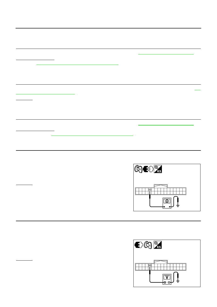
4.
CHECK RGB AREA (YS) SIGNAL FOR AV (NAVI) CONTROL UNIT
1.
Connect AV (NAVI) control unit connector.
2.
Turn ignition switch ON.
3.
Display RGB image.
4.
Check voltage between AV (NAVI) control unit harness connec-
tor M210 terminal 50 and ground.
OK or NG
OK
>> Replace front display unit.
NG
>> Replace AV (NAVI) control unit.
50 – Ground
: Continuity should not exist.
SKIB4691E
50 – Ground
: Approx. 5 V
SKIB6893E
Нет комментариевНе стесняйтесь поделиться с нами вашим ценным мнением.
Текст