Infiniti M35/M45 Y50. Manual — part 15
TROUBLE DIAGNOSIS FOR SELF-DIAGNOSTIC ITEMS
ACS-53
[ICC]
C
D
E
F
G
H
I
J
L
M
A
B
ACS
13.
CHECK ICC SENSOR INTEGRATED UNIT STANDARD VOLTAGE
With CONSULT-II
1.
Connect ICC sensor integrated unit connector.
2.
Turn ignition switch ON.
3.
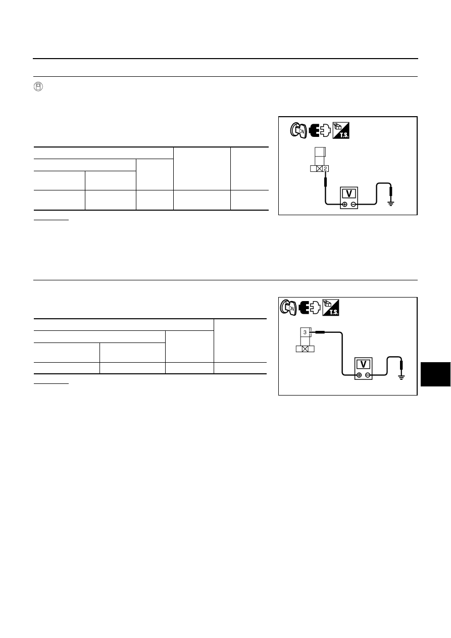
Perform “ACTIVE TEST” (“STOP LAMP”: “STP LMP DRIVE
ON”) with CONSULT-II, check voltage between ICC brake hold
relay harness connector and ground.
OK or NG
OK
>> GO TO 14.
NG
>> 1. Replace ICC sensor integrated unit, and adjust laser beam aiming.
2. Erase DTC and perform ICC system running test. Then perform self-diagnosis of ICC system
again.
14.
CHECK ICC BRAKE HOLD RELAY POWER SUPPLY CIRCUIT
1.
Turn ignition switch ON.
2.
Check voltage between ICC brake hold relay harness connector
and ground.
OK or NG
OK
>> GO TO 15.
NG
>> 1. Repair or replace harness or fuse.
2. Erase DTC and perform ICC system running test. Then perform self-diagnosis of ICC system
again.
Terminals
Condition
Voltage
(Approx.)
(+)
(–)
ICC brake hold
relay connector
Terminal
E80
2 Ground
During
“ACTIVE TEST”
12 V
PKIB9342E
Terminals
Voltage
(Approx.)
(+)
(–)
ICC brake hold relay
connector
Terminal
E80
3 Ground
Battery
voltage
PKIB9343E
ACS-54
[ICC]
TROUBLE DIAGNOSIS FOR SELF-DIAGNOSTIC ITEMS
15.
CHECK HARNESS BETWEEN ICC BRAKE HOLD RELAY AND ECM
1.
Turn ignition switch OFF.
2.
Disconnect ECM connector.
3.
Check continuity between ICC brake hold relay harness connec-
tor (A) and ECM harness connector (B).
4.
Check continuity between ICC brake hold relay harness connec-
tor (A) and ground.
OK or NG
OK
>> GO TO 16.
NG
>> 1. Repair harness between ICC brake hold relay and ECM.
2. Erase DTC and perform ICC system running test. Then perform self-diagnosis of ICC system
again.
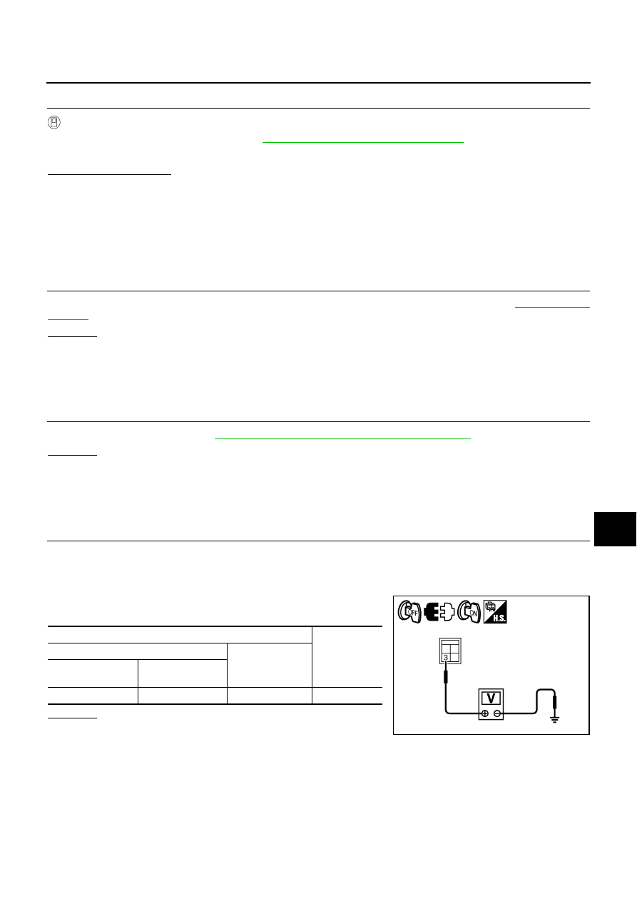
16.
CHECK ICC BRAKE HOLD RELAY
With CONSULT-II
1.
Connect ECM connector and ICC brake hold relay.
2.
Disconnect stop lamp switch connector.
3.
Perform “ACTIVE TEST” (“STOP LAMP”) with CONSULT-II, and make sure that stop lamp is illuminated.
OK or NG
OK
>> GO TO 17.
NG
>> 1. Replace ICC brake hold relay.
2. Erase DTC and perform ICC system running test. Then perform self-diagnosis of ICC system
again.
17.
CHECK STOP LAMP SWITCH WITH ABS DATA MONITOR
With CONSULT-II
With “ABS” “DATA MONITOR”, check if “STOP LAMP SW” are operates normally.
OK or NG
OK
>> GO TO 18.
NG
>> GO TO 20.
18.
PERFORM ECM SELF-DIAGNOSIS
With CONSULT-II
1.
Perform “ENGINE”self-diagnosis. Refer to
EC-123, "CONSULT-II Function (ENGINE)"
EC-826, "CONSULT-II Function (ENGINE)"
(for VK45DE).
2.
Check if malfunction is indicated.
Is malfunction indicated?
YES
>> 1. Repair or replace applicable item.
2. Erase DTC and perform ICC system running test. Then perform self-diagnosis of ICC system
again.
NO
>> GO TO 19.
A
B
Continuity
Connector
Terminal Connector
Terminal
E80
5
M71
101
Yes
A
Ground
Continuity
Connector
Terminal
E80
5
No
PKIB9344E
TROUBLE DIAGNOSIS FOR SELF-DIAGNOSTIC ITEMS
ACS-55
[ICC]
C
D
E
F
G
H
I
J
L
M
A
B
ACS
19.
PERFORM ABS ACTUATOR AND ELECTRIC UNIT (CONTROL UNIT) SELF-DIAGNOSIS
With CONSULT-II
1.
Perform “ABS” self-diagnosis. Refer to
BRC-23, "CONSULT-II Functions (ABS)"
2.
Check if malfunction is indicated.
Is malfunction indicated?
YES
>> 1. Repair or replace applicable item.
2. Erase DTC and perform ICC system running test. Then perform self-diagnosis of ICC system
again.
NO
>> 1. Replace ICC sensor integrated unit, and adjust laser beam aiming.
2. Erase DTC and perform ICC system running test. Then perform self-diagnosis of ICC system
again.
20.
CHECK STOP LAMP SWITCH INSTALLATION AND ADJUSTMENT
Check stop lamp switch for proper installation, and adjust the switch if necessary. Refer to
OK or NG
OK
>> GO TO 21.
NG
>> 1. Adjust stop lamp switch.
2. Erase DTC and perform ICC system running test. Then perform self-diagnosis of ICC system
again.
21.
CHECK STOP LAMP SWITCH
Check stop lamp switch. Refer to
ACS-69, "ICC Brake Switch and Stop Lamp Switch"
OK or NG
OK
>> GO TO 22.
NG
>> 1. Replace stop lamp switch.
2. Erase DTC and perform ICC system running test. Then perform self-diagnosis of ICC system
again.
22.
CHECK STOP LAMP SWITCH POWER SUPPLY CIRCUIT
1.
Turn ignition switch OFF.
2.
Disconnect stop lamp switch connector.
3.
Turn ignition switch ON.
4.
Check voltage between stop lamp switch harness connector and
ground.
OK or NG
OK
>> GO TO 23.
NG
>> 1. Repair or replace harness or fuse.
2. Erase DTC and perform ICC system running test. Then perform self-diagnosis of ICC system
again.
Terminals
Voltage
(Approx.)
(+)
(–)
Stop lamp switch
connector
Terminal
E124
3
Ground
Battery voltage
PKIC0833E

ACS-56
[ICC]
TROUBLE DIAGNOSIS FOR SELF-DIAGNOSTIC ITEMS
23.
CHECK HARNESS BETWEEN STOP LAMP SWITCH AND ABS ACTUATOR AND ELECTRIC UNIT
(CONTROL UNIT)
1.
Turn ignition switch OFF.
2.
Disconnect ABS actuator and electric unit (control unit) connector.
3.
Check continuity between stop lamp switch harness connector
(A) and ABS actuator and electric unit (control unit) harness
connector (B).
4.
Check continuity between stop lamp switch harness connector
(A) and ground.
OK or NG
OK
>> 1. Perform “ABS” self-diagnosis. Refer to
BRC-23, "CONSULT-II Functions (ABS)"
.
2. After repairing or replacing applicable item, erase DTC and perform ICC system running test.
Then perform self-diagnosis of ICC system again.
NG
>> 1. Repair or replace harness between stop lamp switch and ABS actuator and electric unit (control
unit).
2. Erase DTC and perform ICC system running test. Then perform self-diagnosis of ICC system
again.
DTC 14 ECM CIRCUIT
NKS004D8
1.
PERFORM ICC SENSOR INTEGRATED UNIT SELF-DIAGNOSIS
1.
Perform self-diagnosis.
2.
Check if “CAN COMM CIRCUIT [U1000]” (DTC 100) other than “ECM CIRCUIT [C1A14]” (DTC 14) is indi-
cated in self-diagnosis item in the display.
Is it indicated?
YES
>> 1. CAN communication inspection. Refer to
ACS-61, "DTC 100 CAN COMM CIRCUIT"
2. After repairing or replacing applicable item, erase DTC and perform ICC system running test.
Then perform self-diagnosis of ICC system again.
NO
>> GO TO 2.
2.
PERFORM ECM SELF-DIAGNOSIS
With CONSULT-II
1.
Perform “ENGINE” self-diagnosis. Refer to
EC-123, "CONSULT-II Function (ENGINE)"
(for VQ35DE) or
EC-826, "CONSULT-II Function (ENGINE)"
(for VK45DE).
2.
Check if malfunction is indicated.
Is malfunction indicated?
YES
>> 1. Repair or replace applicable item.
2. Erase DTC and perform ICC system running test. Then perform self-diagnosis of ICC system
again.
NO
>> 1. Replace ICC sensor integrated unit, and adjust laser beam aiming.
2. Erase DTC and perform ICC system running test. Then perform self-diagnosis of ICC system
again.
A
B
Continuity
Connector
Terminal Connector
Terminal
E124
4
E30
30
Yes
A
Ground
Continuity
Connector
Terminal
E124
4
No
PKIC0834E
Нет комментариевНе стесняйтесь поделиться с нами вашим ценным мнением.
Текст