Infiniti M35/M45 Y50. Manual — part 226
REMOVAL AND INSTALLATION
AV-281
[WITH MOBILE ENTERTAINMENT SYSTEM]
C
D
E
F
G
H
I
J
L
M
A
B
AV
3.
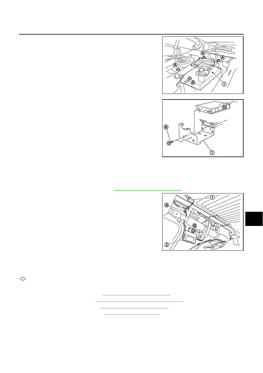
Remove screws (A).
4.
Disconnect connector and remove satellite radio tuner (1) from
trunk room side.
5.
Disconnect screws (A), and remove bracket (1).
INSTALLATION
Installation is the reverse order of removal.
Antenna Amp
NKS004BS
REMOVAL
1.
Remove rear pillar finisher (RH). Refer to
EI-37, "Removal and Installation"
2.
Disengaged the clip (A) to separate glass terminal (1).
3.
Remove screw (B) and remove antenna amp (2) from vehicle.
INSTALLATION
Installation is the reverse order of removal.
Satellite Radio Antenna
NKS004BT
: Vehicle front
REMOVAL
1.
Remove rear pillar finisher. Refer to
EI-37, "Removal and Installation"
2.
Remove personal lamp. Refer to
LT-289, "REMOVAL AND INSTALLATION"
3.
Remove assist grip (rear). Refer to
EI-52, "Removal and Installation"
4.
Remove rear display cover. Refer to
5.
Remove head lining assembly (rear) to obtain work space between the head lining assembly and vehicle.
SKIB4396E
SKIB8875E
SKIB4344E
AV-282
[WITH MOBILE ENTERTAINMENT SYSTEM]
REMOVAL AND INSTALLATION
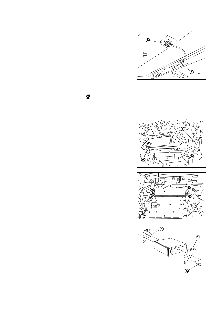
6.
Remove nut (A), and then disconnect connector (1).
7.
Remove satellite radio antenna.
INSTALLATION
Installation is the reverse order of removal.
AV (NAVI) Control Unit
NKS004BV
REMOVAL
1.
Remove glove box cover. Refer to
IP-10, "INSTRUMENT PANEL ASSEMBLY"
2.
Remove screws (A), and remove knee assist protector assem-
bly (1).
3.
Remove screws (A), and disconnect connector.
4.
Remove AV (NAVI) control unit (1).
5.
Remove screws (A) and remove bracket (1).
INSTALLATION
Installation is the reverse order of removal.
SKIB4394E
Roof antenna mounting nut
: 6.0 N·m (0.61 kg-m, 53 in-lb)
SKIB4273E
SKIB4274E
SKIB4275E
REMOVAL AND INSTALLATION
AV-283
[WITH MOBILE ENTERTAINMENT SYSTEM]
C
D
E
F
G
H
I
J
L
M
A
B
AV
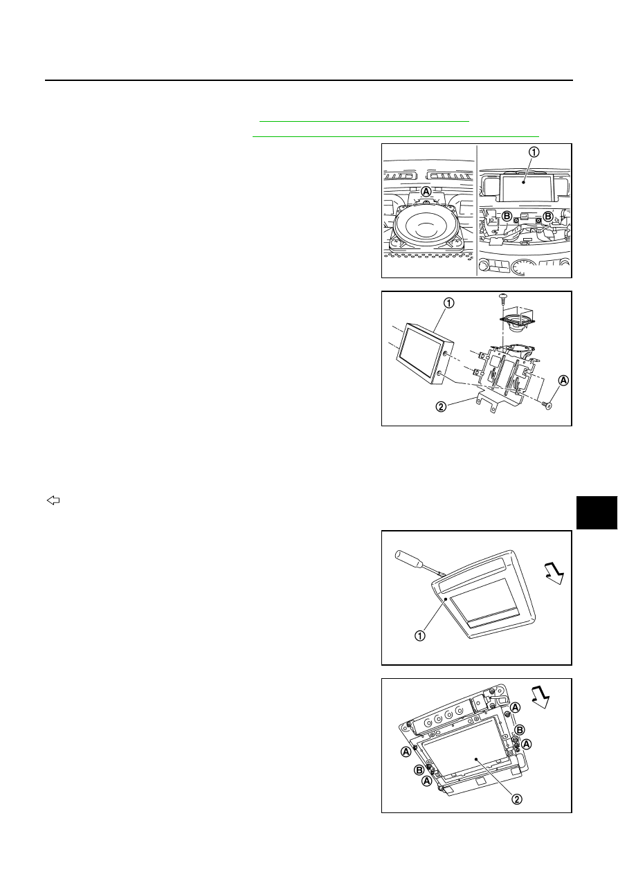
Front Display Unit
NKS004BW
REMOVAL
1.
Remove upper ventilator grille. Refer to
IP-10, "INSTRUMENT PANEL ASSEMBLY"
2.
Remove multifunction switch. Refer to
ATC-123, "Removal and Installation of Multifunction Switch"
3.
Remove screw (A).
4.
Remove screws (B) and disconnect connector, and remove dis-
play (1).
5.
Remove screws (A) separate front display (1) unit from bracket
(2).
INSTALLATION
Installation is the reverse order of removal.
Rear Display Unit
NKS004BX
: Vehicle front
REMOVAL
1.
Insert cloth-covered driver into gaps between rear display cover
(1) and headlining, and remove rear display cover (1).
2.
Remove nuts (A) and plastic nuts (B).
3.
Disconnect connector, and remove rear display unit (2).
SKIB4373E
SKIB4391E
SKIB4354E
SKIB4355E
AV-284
[WITH MOBILE ENTERTAINMENT SYSTEM]
REMOVAL AND INSTALLATION
INSTALLATION
Installation is the reverse order if removal.
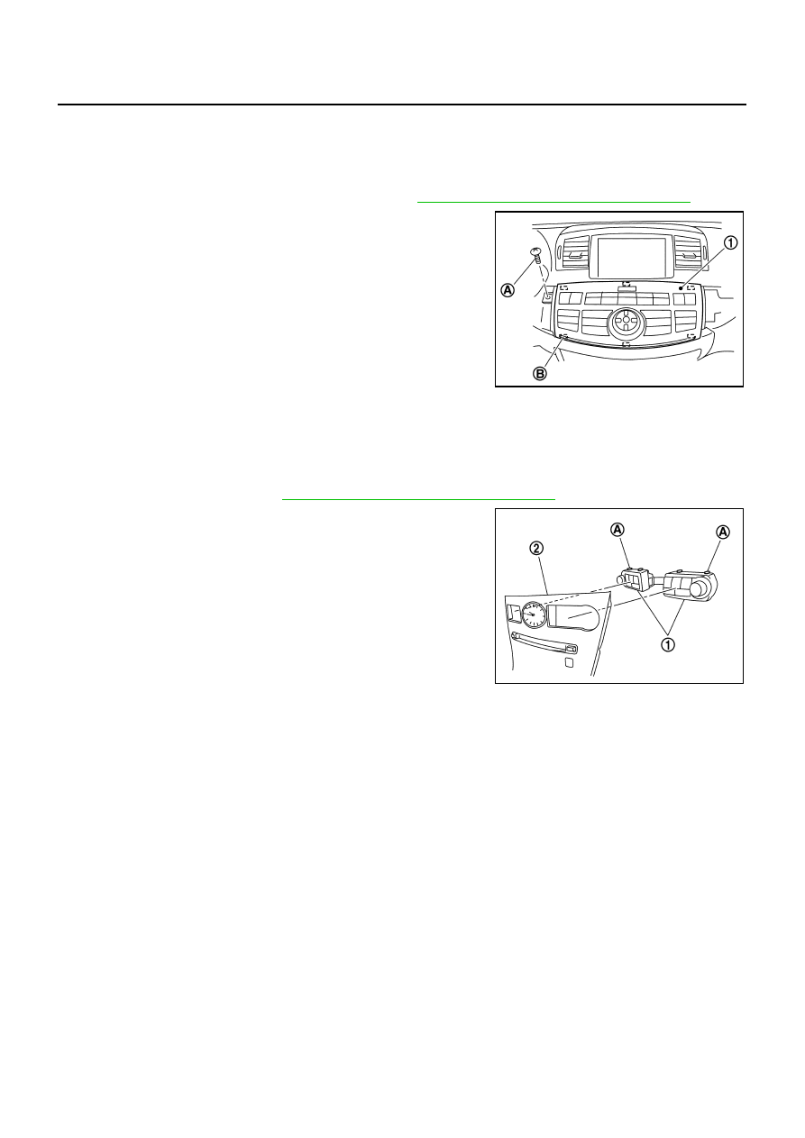
Multifunction Switch
NKS004BY
REMOVAL
1.
Remove instrument panel finisher B and C. Refer to
IP-10, "INSTRUMENT PANEL ASSEMBLY"
2.
Remove screw (A).
3.
Disengage tabs (B) and connector to separate multifunction
switch (1) from instrument panel.
INSTALLATION
Installation is the reverse order of removal.
Preset Switch
NKS004BZ
REMOVAL
1.
Remove cluster lid C. Refer to
IP-10, "INSTRUMENT PANEL ASSEMBLY"
2.
Disengage tabs (A) to separate preset switch (1) from cluster lid
C (2).
INSTALLATION
Installation is the reverse order of removal.
SKIB4276E
SKIB4277E
Нет комментариевНе стесняйтесь поделиться с нами вашим ценным мнением.
Текст