Infiniti M35/M45 Y50. Manual — part 993
PR-1
PROPELLER SHAFT
D DRIVELINE/AXLE
CONTENTS
C
E
F
G
H
I
J
K
L
M
SECTION
PR
A
B
PR
PROPELLER SHAFT
PREPARATION . . . . . . . . . . . . . . ... 2
Special Service Tools . . . . . . . . . . . ... 2
Commercial Service Tools . . . . . . . . . . 2
NOISE, VIBRATION AND HARSHNESS (NVH)
TROUBLESHOOTING . . . . . . . . . . . . 3
NVH Troubleshooting Chart . . . . . . . . . . 3
FRONT PROPELLER SHAFT . . . . . . . . . 4
On-Vehicle Inspection . . . . . . . . . . . .. 4
APPEARANCE AND NOISE INSPECTION . . .. 4
PROPELLER SHAFT VIBRATION . . . . . . 4
Components . . . . . . . . . . . . . . . . 4
Removal and Installation . . . . . . . . . . .. 5
REAR PROPELLER SHAFT . . . . . . . . . .. 6
On-Vehicle Inspection . . . . . . . . . . . .. 6
APPEARANCE AND NOISE INSPECTION . . .. 6
PROPELLER SHAFT VIBRATION . . . . . . 6
Components . . . . . . . . . . . . . . . . 7
Removal and Installation . . . . . . . . . . .. 8
Disassembly and Assembly of Center Bearing (For
3S80A-1VL107 and 3F80A-1VL107 Type) . . . . 11
DISASSEMBLY . . . . . . . . . . . . ... 11
ASSEMBLY . . . . . . . . . . . . . . . 12
SERVICE DATA AND SPECIFICATIONS (SDS) . .. 13
General Specifications . . . . . . . . . . . 13
2WD MODELS . . . . . . . . . . . . . 13
AWD MODELS . . . . . . . . . . . . . 13
Journal Axial Play . . . . . . . . . . . . ... 14
Propeller Shaft Runout . . . . . . . . . . ... 14
PR-2
PREPARATION
PREPARATION
PFP:00002
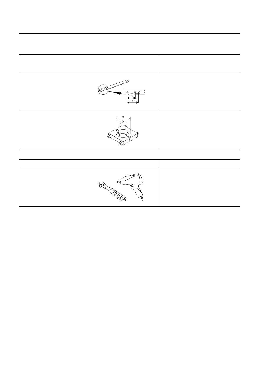
Special Service Tools
NDS000E7
The actual shapes of Kent-Moore tools may differ from those of special service tools illustrated here.
Commercial Service Tools
NDS000E8
Tool number
(Kent-Moore No.)
Tool name
Description
KV40104000
(
—
)
Flange wrench
a: 85 mm (3.35 in)
b: 65 mm (2.56 in)
Removing and installing center flange lock nut
ST30031000
(J-22912-01)
Puller
a: 90 mm (3.54 in) dia.
b: 50 mm (1.97 in) dia.
Removing rear propeller shaft center bearing
NT659
NT411
Tool name
Description
Power tool
Loosening bolts and nuts
PBIC0190E
NOISE, VIBRATION AND HARSHNESS (NVH) TROUBLESHOOTING
PR-3
C
E
F
G
H
I
J
K
L
M
A
B
PR
NOISE, VIBRATION AND HARSHNESS (NVH) TROUBLESHOOTING
PFP:00003
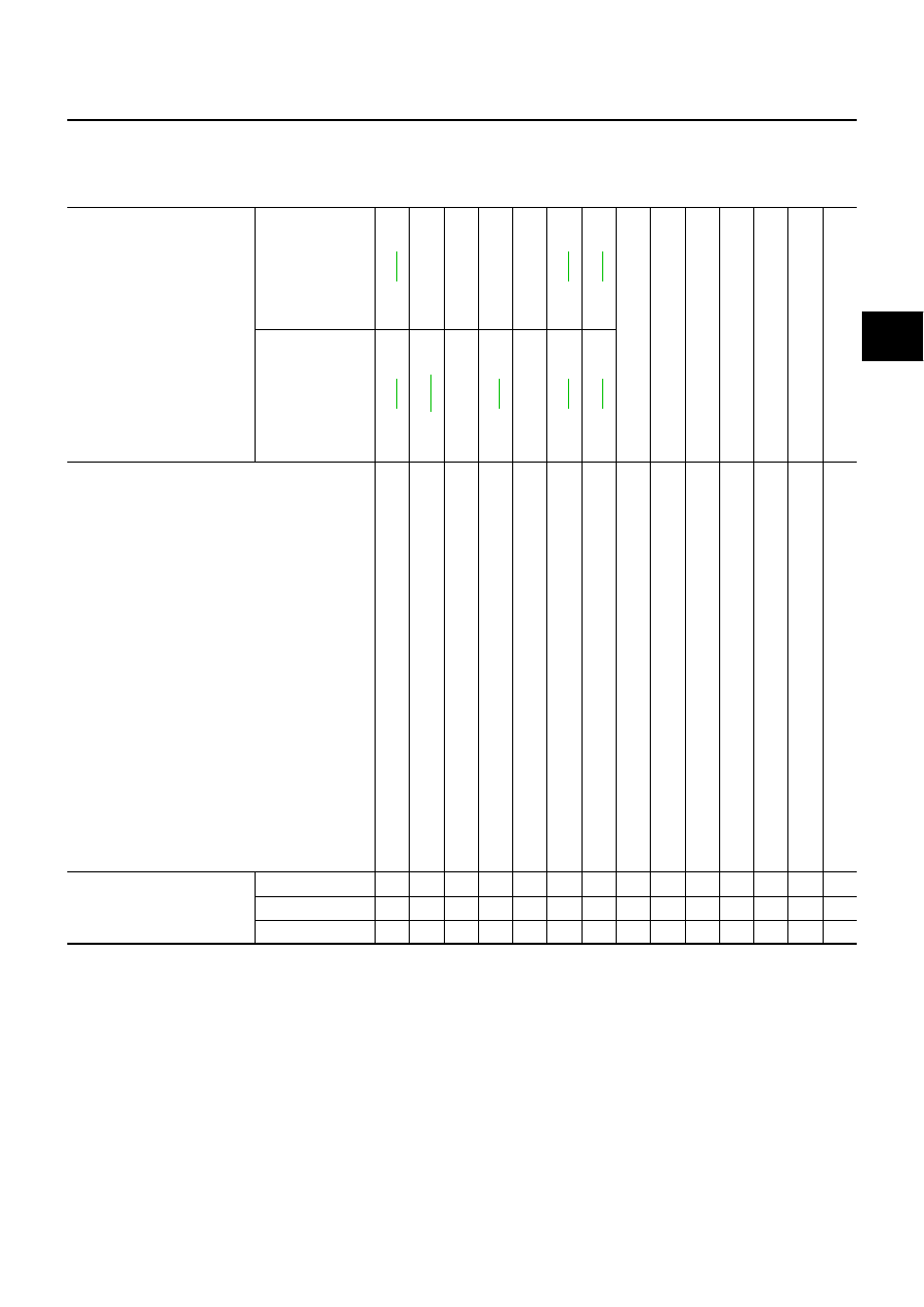
NVH Troubleshooting Chart
NDS000E9
Use the chart below to help you find the cause of the symptom. If necessary, repair or replace these parts.
×
: Applicable
Reference page
Front
—
—
—
—
N
V
H in
FFD a
n
d
RFD s
e
c
tio
n
N
V
H in
F
AX, RAX,
FSU a
n
d
RSU s
e
c
ti
o
n
N
V
H
in
W
T
s
e
c
tio
n
N
V
H
in
W
T
s
e
c
tio
n
N
V
H in
RAX s
e
c
ti
o
n
N
V
H in
BR s
e
c
ti
o
n
N
V
H in
PS s
e
c
tio
n
Rear
—
—
Possible cause and SUSPECTED PARTS
U
n
even
r
o
ta
ti
ng
t
o
rque
C
e
nt
e
r bea
ri
ng i
m
p
rop
er
i
n
st
al
la
ti
on
E
xces
s
iv
e
cent
er
b
ear
in
g a
x
ia
l en
d p
la
y
C
e
nt
e
r bea
ri
ng m
ount
ing (
insu
la
tor
) cr
ack
s
,
da
m
a
ge or
de
te
ri
or
a
ti
o
n
E
xces
s
iv
e j
o
in
t angl
e
R
o
ta
ti
on i
m
b
a
la
nce
E
xces
s
iv
e r
u
n
out
DIFFERENTIAL
A
X
LE AND
SUSPENSION
TI
R
E
S
ROAD W
H
EEL
DRIVE SHAFT
BR
AK
E
S
S
T
EERI
N
G
Symptom
Noise
×
×
×
×
×
×
×
×
×
×
×
×
×
×
Shake
×
×
×
×
×
×
×
×
Vibration
×
×
×
×
×
×
×
×
×
×
×
PR-4
FRONT PROPELLER SHAFT
FRONT PROPELLER SHAFT
PFP:37200
On-Vehicle Inspection
NDS000EA
APPEARANCE AND NOISE INSPECTION
●
Check the propeller shaft tube surface for dents or cracks. If damaged, replace propeller shaft assembly.
PROPELLER SHAFT VIBRATION
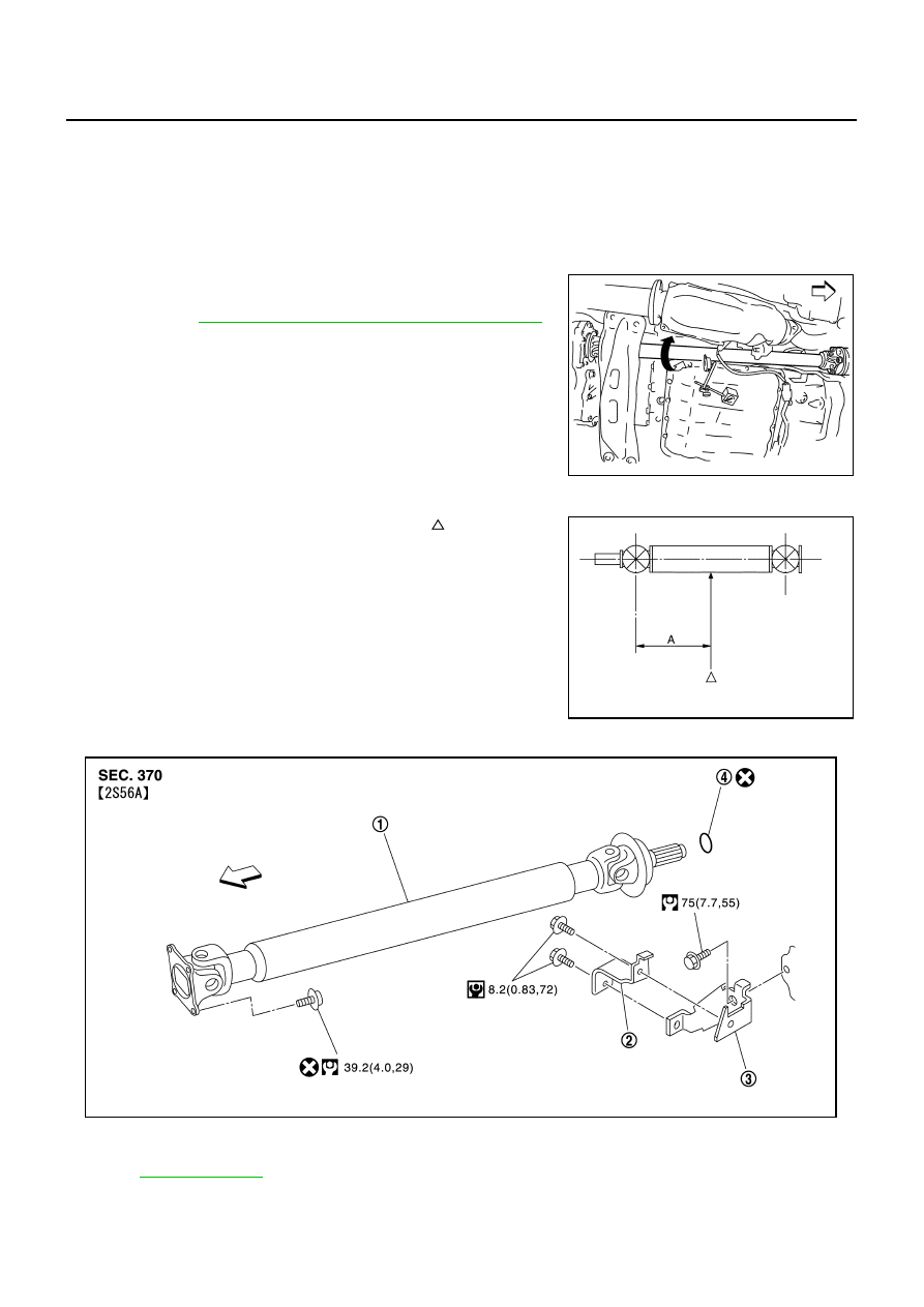
If vibration is present at high speed, inspect propeller shaft runout first.
1.
Measure propeller shaft runout at runout measuring point by
rotating final drive companion flange with hands. For measuring
point, refer to
PR-4, "Propeller Shaft Runout Measuring Point"
2.
If runout still exceeds specifications, separate propeller shaft at
final drive companion flange; then rotate companion flange 90,
180, 270 degrees and install propeller shaft.
3.
Check runout again. If runout still exceeds specifications,
replace propeller shaft assembly.
4.
Check the vibration by driving vehicle.
Propeller Shaft Runout Measuring Point
●
Propeller shaft runout measuring point (Point “ ”)
Components
NDS000EB
Propeller shaft runout limit
: 0.8 mm (0.031 in)
PDIA0767J
Dimension
A: 381.5 mm (15.01 in)
PDIA0768J
1.
Propeller shaft assembly
2.
Heat bracket (A)
3.
Heat bracket (B)
4.
O-ring
, for the symbols in the figure.
PDIA0769J
Нет комментариевНе стесняйтесь поделиться с нами вашим ценным мнением.
Текст