Infiniti M35/M45 Y50. Manual — part 11
TROUBLE DIAGNOSIS - GENERAL DESCRIPTION
ACS-37
[ICC]
C
D
E
F
G
H
I
J
L
M
A
B
ACS
1.
CHECK FUSE
Check if the fuse is blown.
OK or NG
OK
>> GO TO 2.
NG
>> If fuse is blown, be sure to eliminate cause of malfunction before installing new fuse.
2.
CHECK ICC SYSTEM DISPLAY
Check if dot matrix LCD in the combination meter illuminates. Refer to
DI-17, "Self-Diagnosis Mode of Combi-
OK or NG
OK
>> GO TO 3.
NG
>> Check combination meter. Refer to
DI-18, "HOW TO PERFORM TROUBLE DIAGNOSIS"
3.
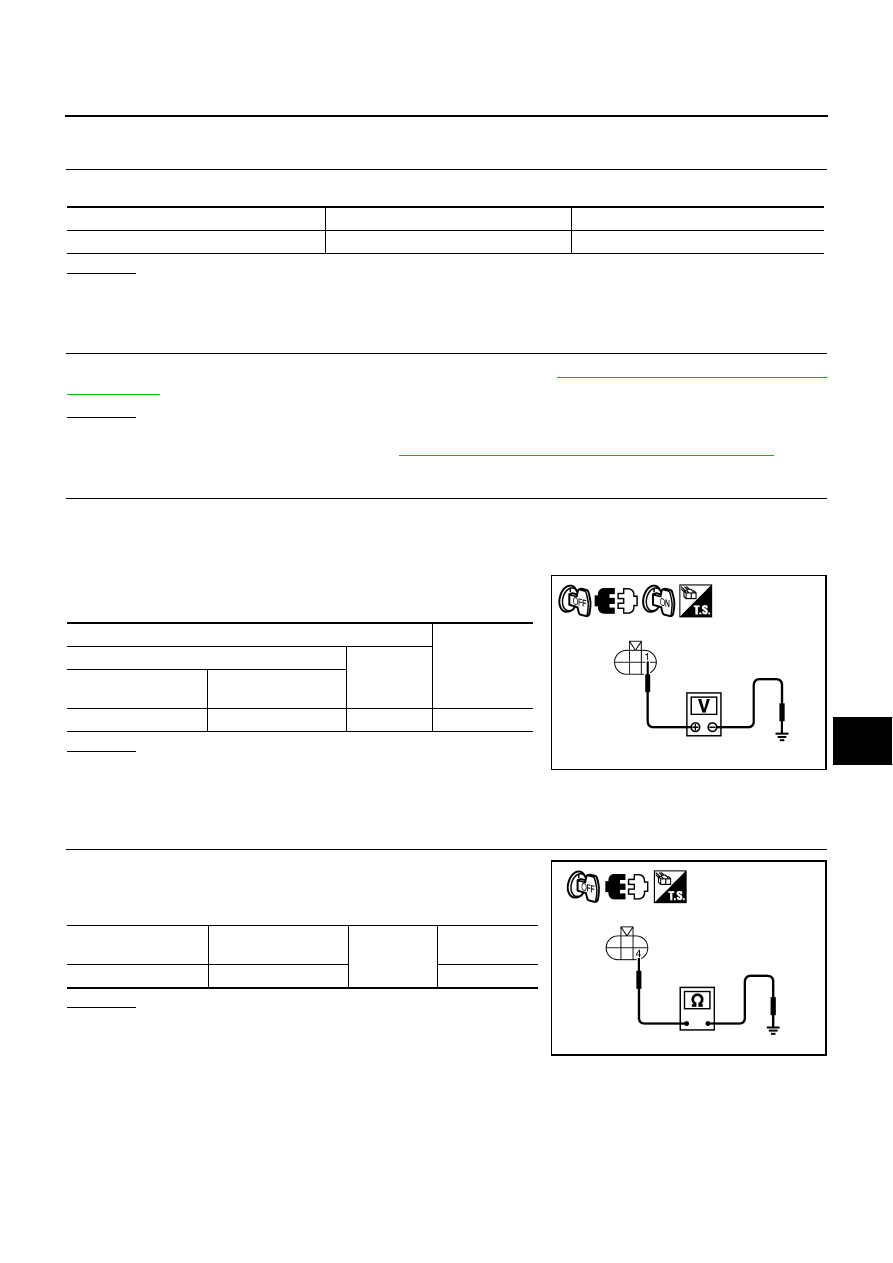
CHECK POWER SUPPLY CIRCUIT FOR ICC SENSOR INTEGRATED UNIT
1.
Turn ignition switch OFF.
2.
Disconnect ICC sensor integrated unit connector.
3.
Turn ignition switch ON.
4.
Check voltage between ICC sensor integrated unit harness con-
nector and ground.
OK or NG
OK
>> GO TO 4.
NG
>> Repair or replace ICC sensor integrated unit power sup-
ply harness.
4.
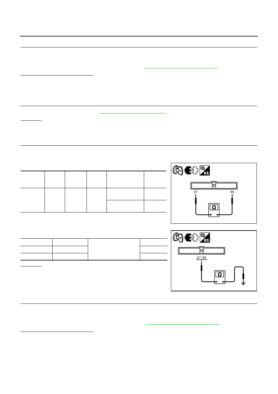
CHECK GROUND CIRCUIT FOR ICC SENSOR INTEGRATED UNIT
1.
Turn ignition switch OFF.
2.
Check continuity between ICC sensor integrated unit harness
connector and ground.
OK or NG
OK
>> GO TO 5.
NG
>> Repair or replace ICC sensor integrated unit ground har-
ness.
Unit
Power source
Fuse No.
ICC sensor integrated unit
Ignition switch ON or START
82
Terminals
Voltage
(Approx.)
(+)
(–)
ICC sensor integrated
unit connector
Terminal
E61
1 Ground
Battery
voltage
PKIB8375E
ICC sensor integrated
unit connector
Terminal
Ground
Continuity
E61
4
Yes
PKIB8376E
ACS-38
[ICC]
TROUBLE DIAGNOSIS - GENERAL DESCRIPTION
5.
CHECK CONNECTOR FOR ICC SENSOR INTEGRATED UNIT
1.
Check terminals for bend and looseness.
2.
Securely connect ICC sensor integrated unit connector again.
3.
Perform self-diagnosis without CONSULT-II. Refer to
Can self-diagnosis be performed?
YES
>> Check connector. (Check connector housing for disconnected, loose, bent, and collapsed termi-
nals. If any malfunction is detected, repair applicable part.)
NO
>> GO TO 6.
6.
CHECK ICC STEERING SWITCH
Check ICC steering switch. Refer to
.
OK or NG
OK
>> GO TO 7.
NG
>> Replace ICC steering switch.
7.
CHECK HARNESS BETWEEN ECM AND ICC STEERING SWITCH
1.
Turn ignition switch OFF.
2.
Disconnect ECM connector.
3.
Check resistance between ECM harness connector.
4.
Check continuity between ECM harness connector and ground.
OK or NG
OK
>> GO TO 8.
NG
>> Repair or replace harness between ECM and ICC steer-
ing switch.
8.
CHECK CONNECTOR FOR ECM
1.
Check terminals for bend and looseness.
2.
Securely connect ECM connector again.
3.
Perform self-diagnosis without CONSULT-II. Refer to
Can self-diagnosis be performed?
YES
>> Check connector. (Check connector housing for disconnected, loose, bent, and collapsed termi-
nals. If any malfunction is detected, repair applicable part.)
NO
>> GO TO 9.
ECM
connector
Terminal
ECM
connector
Terminal Condition
Resis-
tance
(Approx.)
F108
67
M71
99
When MAIN switch
pressed
0
Ω
When MAIN switch
released
5.5 k
Ω
PKIB8377E
ECM connector
Terminal
Ground
Continuity
F108
67 No
M71
99 No
PKIB8378E

TROUBLE DIAGNOSIS - GENERAL DESCRIPTION
ACS-39
[ICC]
C
D
E
F
G
H
I
J
L
M
A
B
ACS
9.
CHECK CAN COMMUNICATION
1.
Perform self-diagnosis with CONSULT-II.
2.
Check if “DTC 100 CAN COMM CIRCUIT” is indicated in self-diagnosis item in the display.
Is it indicated?
YES
>> 1. CAN communication inspection. Refer to
ACS-61, "DTC 100 CAN COMM CIRCUIT"
2. After repairing or replacing applicable item, erase DTC and perform ICC system running test.
Then perform self-diagnosis of ICC system again.
NO
>> 1. Perform “ENGINE” self-diagnosis. Refer to
EC-123, "CONSULT-II Function (ENGINE)"
(for
VQ35DE) or
EC-826, "CONSULT-II Function (ENGINE)"
2. After repairing or replacing applicable item, erase DTC and perform ICC system running test.
Then perform self-diagnosis of ICC system again.

ACS-40
[ICC]
TROUBLE DIAGNOSIS FOR SELF-DIAGNOSTIC ITEMS
TROUBLE DIAGNOSIS FOR SELF-DIAGNOSTIC ITEMS
PFP:25962
Diagnostic Trouble Code (DTC) Chart
NKS004CZ
×
: Applicable
DTC
No.
CONSULT-II
screen terms
ICC
system
warning
lamp
Fail-safe
Malfunctions detected where...
Refer-
ence
page
Vehicle-
to-
vehicle
distance
control
mode
Conven-
tional
(fixed
speed)
cruise
control
mode
Brake
assist
(with
preview
function)
0
CONTROL UNIT
[C1A00]
×
×
×
×
●
ICC sensor integrated unit internal
malfunction.
1
POWER SUPPLY CIR
[C1A01]
×
×
×
×
●
ICC sensor integrated unit power
supply voltage is excessively low
(less than 8V).
2
POWER SUPPLY CIR 2
[C1A02]
×
×
×
×
●
ICC sensor integrated unit power
supply voltage is excessively high
(more than 19V).
3
VHCL SPEED SE CIRC
[C1A03]
×
×
×
×
●
Wheel sensor malfunction.
●
ABS actuator and electric unit
(control unit) malfunction.
●
A/T vehicle speed sensor mal-
function.
●
TCM malfunction.
●
ICC sensor integrated unit mal-
function.
4
ABS/TCS/VDC CIRC
[C1A04]
×
×
×
×
●
VDC/TCS/ABS system malfunc-
tion.
5
BRAKE SW/STOP L SW
[C1A05]
×
×
×
×
●
Stop lamp switch harness is open
or shorted.
●
Stop lamp switch is stuck to OFF.
●
ICC brake switch or stop lamp
switch is stuck to ON.
●
ECM malfunction.
●
ABS actuator and electric unit
(control unit) malfunction.
6
OPERATION SW CIRC
[C1A06]
×
×
×
●
ICC steering switch harness or
spiral cable is open or shorted.
●
ICC steering switch malfunction.
12
LASER BEAM OFFCNTR
[C1A12]
×
×
×
●
Laser beam of ICC sensor inte-
grated unit is off the aiming point.
13
STOP LAMP RLY FIX
[C1A13]
×
×
×
●
Normally open terminal of ICC
brake hold relay is stuck.
●
Improper installation of ICC brake
switch or stop lamp switch.
●
ICC brake switch malfunction.
●
ECM malfunction.
●
ABS actuator and electric unit
(control unit) malfunction.
Нет комментариевНе стесняйтесь поделиться с нами вашим ценным мнением.
Текст