Infiniti M35/M45 Y50. Manual — part 476
DTC P0340, P0345 CMP SENSOR (PHASE)
EC-377
[VQ35DE]
C
D
E
F
G
H
I
J
K
L
M
A
EC
2.
CHECK GROUND CONNECTIONS
1.
Turn ignition switch OFF.
2.
Loosen and retighten ground two screws on the body. Refer to
.
OK or NG
OK
>> GO TO 3.
NG
>> Repair or replace ground connections.
3.
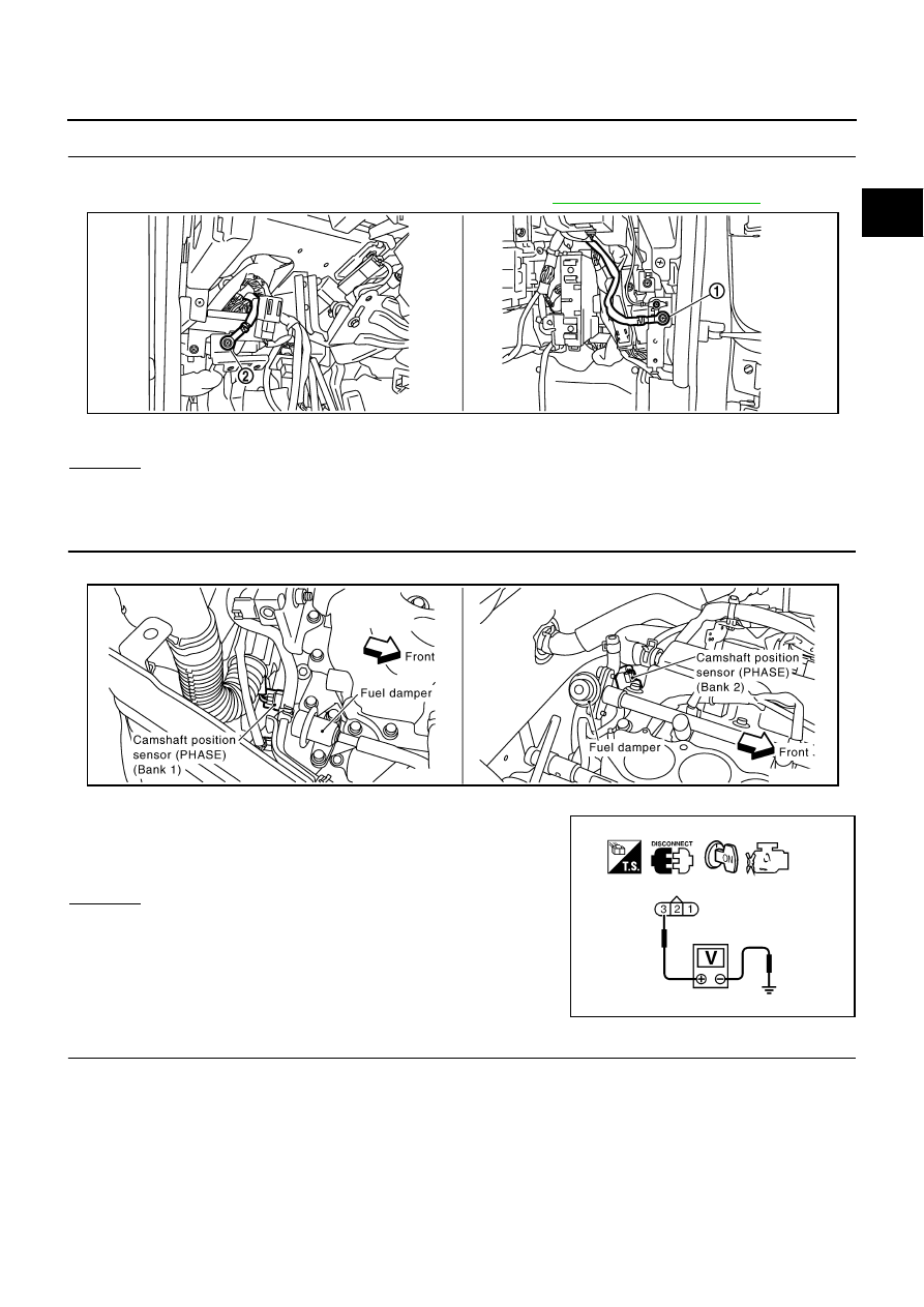
CHECK CAMSHAFT POSITION (CMP) SENSOR (PHASE) POWER SUPPLY CIRCUIT
1.
Disconnect camshaft position (CMP) sensor (PHASE) harness connector.
2.
Turn ignition switch ON.
3.
Check voltage between CMP sensor (PHASE) terminal 3 and
ground with CONSULT-II or tester.
OK or NG
OK
>> GO TO 5.
NG
>> GO TO 4.
4.
DETECT MALFUNCTIONING PART
Check the following.
●
Harness connectors E108, M15
●
Harness connectors F102, M72
●
Harness for open or short between camshaft position sensor (PHASE) and ECM
●
Harness for open or short between camshaft position sensor (PHASE) and IPDM E/R
>> Repair open circuit or short to ground or short to power in harness or connectors.
1.
Body ground M70
2.
Body ground M16
PBIB2782E
Voltage: Battery voltage
PBIB1568E
SEF481Y

EC-378
[VQ35DE]
DTC P0340, P0345 CMP SENSOR (PHASE)
5.
CHECK CMP SENSOR (PHASE) GROUND CIRCUIT FOR OPEN AND SHORT
1.
Turn ignition switch OFF.
2.
Check harness continuity between CMP sensor (PHASE) terminal 1 and ground.
Refer to Wiring Diagram.
3.
Also check harness for short to power.
OK or NG
OK
>> GO TO 7.
NG
>> GO TO 6.
6.
DETECT MALFUNCTIONING PART
Check the following.
●
Harness connectors F102, M72
●
Harness for open or short between CMP sensor (PHASE) and ground
>> Repair open circuit or short to power in harness or connectors.
7.
CHECK CMP SENSOR (PHASE) INPUT SIGNAL CIRCUIT FOR OPEN AND SHORT
1.
Disconnect ECM harness connector.
2.
Check harness continuity between ECM terminal 33 (Bank 1) or 14 (Bank 2) and CMP sensor (PHASE)
terminal 2.
Refer to Wiring Diagram.
3.
Also check harness for short to ground and short to power.
OK or NG
OK
>> GO TO 8.
NG
>> Repair open circuit or short to ground or short to power in harness or connectors.
8.
CHECK CAMSHAFT POSITION SENSOR (PHASE)
Refer to
EC-379, "Component Inspection"
OK or NG
OK
>> GO TO 9.
NG
>> Replace malfunctioning camshaft position sensor (PHASE).
9.
CHECK CAMSHAFT (INT)
Check the following.
●
Accumulation of debris to the signal plate of camshaft rear end
●
Chipping signal plate of camshaft rear end
OK or NG
OK
>> GO TO 10.
NG
>> Remove debris and clean the signal plate of camshaft
rear end or replace camshaft.
Continuity should exist.
Continuity should exist.
SEC905C
DTC P0340, P0345 CMP SENSOR (PHASE)
EC-379
[VQ35DE]
C
D
E
F
G
H
I
J
K
L
M
A
EC
10.
CHECK INTERMITTENT INCIDENT
Refer to
EC-153, "TROUBLE DIAGNOSIS FOR INTERMITTENT INCIDENT"
>> INSPECTION END
Component Inspection
NBS004ZA
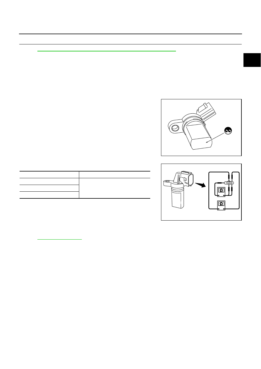
CAMSHAFT POSITION SENSOR (PHASE)
1.
Loosen the fixing bolt of the sensor.
2.
Disconnect camshaft position sensor (PHASE) harness connector.
3.
Remove the sensor.
4.
Visually check the sensor for chipping.
5.
Check resistance as shown in the figure.
Removal and Installation
NBS004ZB
CAMSHAFT POSITION SENSOR (PHASE)
Refer to
PBIB0563E
Terminal No. (Polarity)
Resistance
Ω
[at 25
°
C (77
°
F)]
1 (+) - 2 (-)
Except 0 or
∞
1 (+) - 3 (-)
2 (+) - 3 (-)
PBIB0564E
EC-380
[VQ35DE]
DTC P0420, P0430 THREE WAY CATALYST FUNCTION
DTC P0420, P0430 THREE WAY CATALYST FUNCTION
PFP:20905
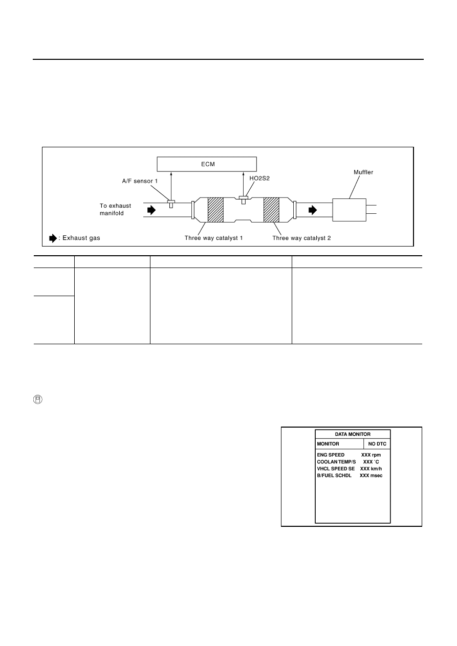
On Board Diagnosis Logic
NBS004ZC
The ECM monitors the switching frequency ratio of air fuel ratio (A/F) sensor 1 and heated oxygen sensor 2.
A three way catalyst 1 with high oxygen storage capacity will indicate a low switching frequency of heated oxy-
gen sensor 2. As oxygen storage capacity decreases, the heated oxygen sensor 2 switching frequency will
increase.
When the frequency ratio of A/F sensor 1 and heated oxygen sensor 2 approaches a specified limit value, the
three way catalyst 1 malfunction is diagnosed.
DTC Confirmation Procedure
NBS004ZD
NOTE:
If DTC Confirmation Procedure has been previously conducted, always turn ignition switch OFF and wait at
least 10 seconds before conducting the next test.
WITH CONSULT-II
TESTING CONDITION:
Do not hold engine speed for more than the specified minutes below.
1.
Turn ignition switch ON and select “DATA MONITOR” mode with
CONSULT-II.
2.
Start engine and warm it up to the normal operating tempera-
ture.
3.
Turn ignition switch OFF and wait at least 10 seconds.
4.
Start engine and keep the engine speed between 3,500 and
4,000 rpm for at least 1 minute under no load.
5.
Let engine idle for 1 minute.
6.
Make sure that “COOLAN TEMP/S” indicates more than 70
°
C
(158
°
F).
If not, warm up engine and go to next step when “COOLAN
TEMP/S” indication reaches to 70
°
C (158
°
F).
7.
Open engine hood.
DTC No.
Trouble diagnosis name
DTC detecting condition
Possible cause
P0420
0420
(Bank 1)
Catalyst system effi-
ciency below threshold
●
Three way catalyst (manifold) does not oper-
ate properly.
●
Three way catalyst (manifold) does not have
enough oxygen storage capacity.
●
Three way catalyst (manifold)
●
Exhaust tube
●
Intake air leaks
●
Fuel injector
●
Fuel injector leaks
●
Spark plug
●
Improper ignition timing
P0430
0430
(Bank 2)
PBIB1923E
SEF189Y
Нет комментариевНе стесняйтесь поделиться с нами вашим ценным мнением.
Текст