Infiniti M35/M45 Y50. Manual — part 971
IPDM E/R (INTELLIGENT POWER DISTRIBUTION MODULE ENGINE ROOM)
PG-29
C
D
E
F
G
H
I
J
L
M
A
B
PG
Check IPDM E/R Power Supply and Ground Circuit
NKS004EA
1.
CHECK FUSES AND FUSIBLE LINKS
Check for blown fuses and fusible link.
OK or NG
OK
>> GO TO 2.
NG
>> If fuse or fusible link is blown, be sure to eliminate cause of malfunction before installing new fuse
or fusible link.
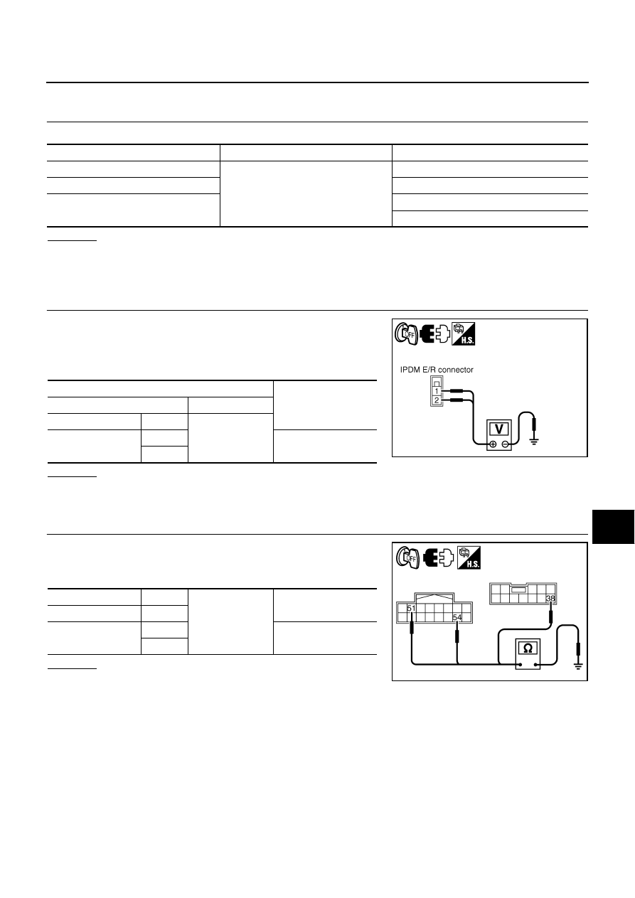
2.
CHECK POWER SUPPLY CIRCUIT
1.
Turn ignition switch OFF.
2.
Disconnect IPDM E/R harness connector.
3.
Check voltage between IPDM E/R harness connector and
ground.
OK or NG
OK
>> GO TO 3.
NG
>> Repair harness or connector.
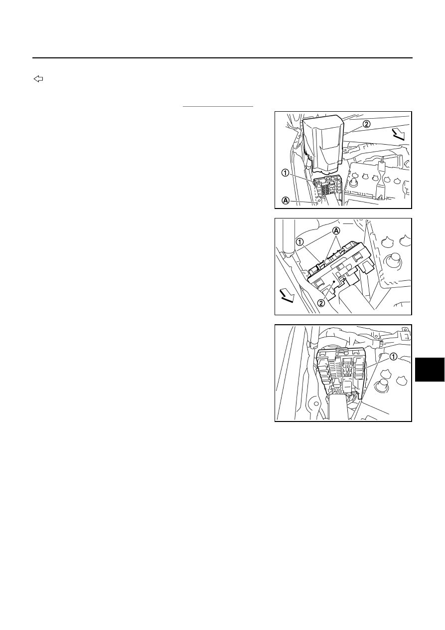
3.
CHECK GROUND CIRCUIT
1.
Disconnect IPDM E/R harness connectors.
2.
Check continuity between IPDM E/R harness connectors and
ground.
OK or NG
OK
>> INSPECTION END
NG
>> Repair harness or connector.
Terminal No.
Power source
Fuse and fusible link No.
1
Battery
E
2
C
—
71
78
Terminals
Voltage
(+)
(-)
IPDM E/R connector
Terminal
Ground
E3
1
Battery voltage
2
PKIB6562E
IPDM E/R connector
Terminal
Ground
Continuity
E8
38
E9
51
Yes
54
PKIC0906E

PG-30
IPDM E/R (INTELLIGENT POWER DISTRIBUTION MODULE ENGINE ROOM)
Inspection with CONSULT-II (Self-Diagnosis)
NKS004EB
CAUTION:
If CONSULT-II is used with no connection of CONSULT-II CONVERTER, malfunctions might be
detected in self-diagnosis depending on control unit which carry out CAN communication.
1.
CHECK SELF DIAGNOSTIC RESULT
1.
Connect CONSULT-II and select “IPDM E/R” on the “SELECT SYSTEM” screen.
2.
Select “SELF-DIAG RESULTS” on the “SELECT DIAG MODE” screen.
3.
Check display content in self diagnostic results.
NOTE:
The details for display of the period are as follows:
●
CRNT: Error currently detected with IPDM E/R.
●
PAST: Error detected in the past and memorized with IPDM E/R.
Contents displayed
NO DTC IS DETECTED.FURTHER TESTING MAY BE REQUIRED.>>INSPECTION END
CAN COMM CIRC>>After print-out of the monitor items, refer to
LAN-50, "CAN System Specification Chart"
.
CONSULT-II display
CONSULT-II
display code
TIME
Details of diagnosis result
CRNT
PAST
NO DTC IS DETECTED.
FURTHER TESTING MAY BE REQUIRED.
-
-
-
No malfunction
CAN COMM CIRC
U1000
×
×
Any of or several items below have errors.
●
TRANSMIT DIAG
●
ECM
●
BCM/SEC
IPDM E/R (INTELLIGENT POWER DISTRIBUTION MODULE ENGINE ROOM)
PG-31
C
D
E
F
G
H
I
J
L
M
A
B
PG
Removal and Installation of IPDM E/R
NKS004EC
: Vehicle front
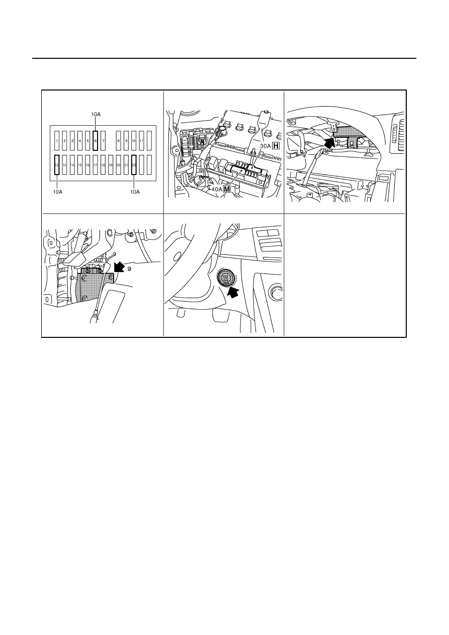
REMOVAL
1.
Remove cowl top cover (RH). Refer to
.
2.
Disengage pawls (A) on both side of IPDM E/R cover B (1),
remove IPDM E/R cover A (2).
3.
While pushing pawl (A) on backside of IPDM E/R cover B (1)
toward vehicle front to unlock, lift up IPDM E/R (2).
4.
Disengage pawls on both side of IPDM E/R (1), remove IPDM E/
R cover B.
5.
Remove harness connector from IPDM E/R (1) and remove
IPDM E/R (1).
INSTALLATION
Installation is the reverse order of removal.
SKIB4109E
SKIB4110E
SKIB4111E
PG-32
PDU (POWER DISTRIBUTION UNIT)
PDU (POWER DISTRIBUTION UNIT)
PFP:285F1
Component Parts and Harness Connector Location
NKS004ED
System Description
NKS004EE
●
PDU (Power Distribution Unit) is the unit that executes the power distribution with the control signal from
the Intelligent Key unit, instead of the mechanical power supply mechanism by conventional key cylinder.
●
The push-button ignition switch is operable when the Intelligent Key is within the detention area of the
interior antenna or is inserted to the key slot.
●
The push-button ignition switch operation is input to the Intelligent Key unit as a request signal. Then, the
Intelligent Key unit processes the request signal and orders the PDU to switch into the appropriate power
supply position.
NOTE:
The prerequisite for starting the engine varies by the state of brake pedal, A/T selector lever, and vehicle
speed.
●
PDU distributes power to each power supply circuit according to the request signal received.
●
The power supply position can be confirmed by illumination of the indicators in the upper surroundings of
the push-button ignition switch.
PUSH-BUTTON IGNITION SWITCH OPERATING PROCEDURE
The power supply position switching operation can be performed by the following operation.
NOTE:
●
When an Intelligent Key is within the detection area of inside antenna and when it is inserted to the key
slot, it is equivalent to the operations below.
●
When starting the engine, the Intelligent Key unit monitors the engine start conditions (brake pedal operat-
ing condition, A/T selector lever position, and vehicle speed).
1.
Fuse block (J / B) fuse layout
2.
Fuse and fusible link box
3.
PDU (power distribution unit)
M30,M31
4.
Intelligent key unit M32,M33
5.
Push-button ignition switch M27
PIIB6094E
Нет комментариевНе стесняйтесь поделиться с нами вашим ценным мнением.
Текст