Infiniti M35/M45 Y50. Manual — part 695
DTC P1553 BATTERY CURRENT SENSOR
EC-1253
[VK45DE]
C
D
E
F
G
H
I
J
K
L
M
A
EC
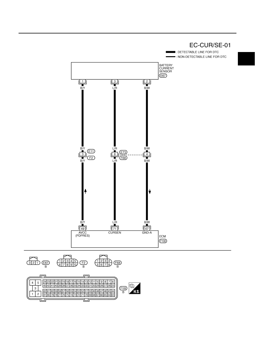
Wiring Diagram
NBS005LX
TBWT1064E
EC-1254
[VK45DE]
DTC P1553 BATTERY CURRENT SENSOR
Specification data are reference values and are measured between each terminal and ground.
CAUTION:
Do not use ECM ground terminals when measuring input/output voltage. Doing so may result in dam-
age to the ECM's transistor. Use a ground other than ECM terminals, such as the ground.
*: Before measuring the terminal voltage, confirm that the battery is fully charged. Refer to
SC-5, "SPECIFIC GRAVITY CHECK"
Diagnostic Procedure
NBS005LY
1.
CHECK GROUND CONNECTIONS
1.
Turn ignition switch OFF.
2.
Loosen and retighten ground screws on the body.
Refer to
OK or NG
OK
>> GO TO 2.
NG
>> Repair or replace ground connections.
TER-
MINAL
NO.
WIRE
COLOR
ITEM
CONDITION
DATA (DC Voltage)
49
B/Y
Sensor power supply
(Battery current sensor)
[Ignition switch: ON]
Approximately 5V
67
B/W
Sensor ground
(Battery current sensor)
[Engine is running]
●
Warm-up condition
●
Idle speed
Approximately 0V
71
L/R
Battery current sensor
[Engine is running]
●
Battery: Fully charged*
●
Idle speed
Approximately 2.6 - 3.5V
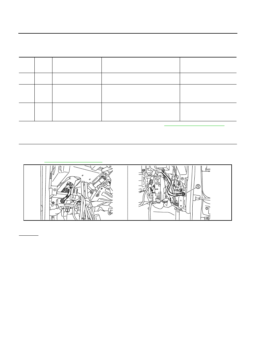
1.
Body ground M70
2.
Body ground M16
PBIB2782E
DTC P1553 BATTERY CURRENT SENSOR
EC-1255
[VK45DE]
C
D
E
F
G
H
I
J
K
L
M
A
EC
2.
CHECK BATTERY CURRENT SENSOR POWER SUPPLY CIRCUIT
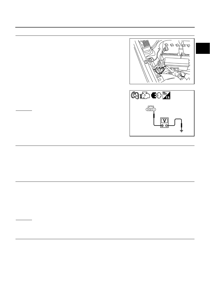
1.
Disconnect battery current sensor (1) harness connector.
2.
Turn ignition switch ON.
3.
Check voltage between battery current sensor terminal 1 and
ground with CONSULT-II or tester.
OK or NG
OK
>> GO TO 4.
NG
>> GO TO 3.
3.
DETECT MALFUNCTIONING PART
Check the following.
●
Harness connectors E11, F2
●
Harness for open or short between battery current sensor and ECM
>> Repair open circuit or short to ground or short to power in harness or connectors.
4.
CHECK BATTERY CURRENT SENSOR GROUND CIRCUIT FOR OPEN AND SHORT
1.
Turn ignition switch OFF.
2.
Disconnect ECM harness connector.
3.
Check harness continuity between battery current sensor terminal 2 and ECM terminal 67.
Refer to Wiring Diagram.
4.
Also check harness for short to ground and short to power.
OK or NG
OK
>> GO TO 6.
NG
>> GO TO 5.
5.
DETECT MALFUNCTIONING PART
Check the following.
●
Harness connectors E73, F68
●
Harness for open or short between battery current sensor and ECM
>> Repair open circuit or short to ground or short to power in harness or connectors.
PBIB2685E
Voltage: Approximately 5V
PBIA9891J
Continuity should exist.
EC-1256
[VK45DE]
DTC P1553 BATTERY CURRENT SENSOR
6.
CHECK BATTERY CURRENT SENSOR INPUT SIGNAL CIRCUIT FOR OPEN AND SHORT
1.
Check harness continuity between battery current sensor terminal 3 and ECM terminal 71.
Refer to Wiring Diagram.
2.
Also check harness for short to ground and short to power.
OK or NG
OK
>> GO TO 8.
NG
>> GO TO 7.
7.
DETECT MALFUNCTIONING PART
Check the following.
●
Harness connectors E73, F68
●
Harness for open or short between battery current sensor and ECM
>> Repair open circuit or short to ground or short to power in harness or connectors.
8.
CHECK BATTERY CURRENT SENSOR
Refer to
EC-1256, "Component Inspection"
OK or NG
OK
>> GO TO 9.
NG
>> Replace battery negative cable assembly.
9.
CHECK INTERMITTENT INCIDENT
Refer to
EC-857, "TROUBLE DIAGNOSIS FOR INTERMITTENT INCIDENT"
.
>> INSPECTION END
Component Inspection
NBS005LZ
BATTERY CURRENT SENSOR
1.
Reconnect harness connectors disconnected.
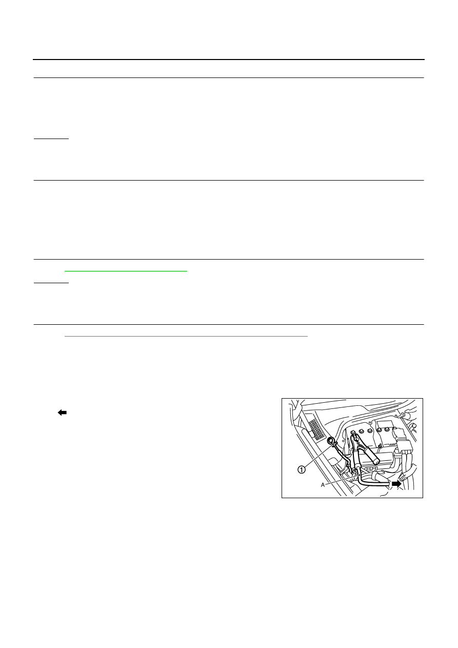
2.
Disconnect battery negative cable (1).
●
: To body ground
3.
Install jumper cable A between battery negative terminal and
body ground.
4.
Turn ignition switch ON.
Continuity should exist.
PBIB2724E
Нет комментариевНе стесняйтесь поделиться с нами вашим ценным мнением.
Текст