Infiniti M35/M45 Y50. Manual — part 734

ICC BRAKE SWITCH
EC-1409
[VK45DE]
C
D
E
F
G
H
I
J
K
L
M
A
EC
10.
DETECT MALFUNCTIONING PART
Check the following.
●
Fuse block (J/B) connector E101
●
10A fuse
●
Harness for open or short between battery and stop lamp switch
●
Harness for open or short between battery and ICC brake hold relay
>> Repair open circuit or short to ground or short to power in harness or connectors.
11.
CHECK STOP LAMP SWITCH INPUT SIGNAL CIRCUIT FOR OPEN AND SHORT
1.
Disconnect ECM harness connector.
2.
Check harness continuity between the following;
ECM terminal 101 and stop lamp switch terminal 2,
ECM terminal 101 and ICC brake hold relay terminal 5.
Refer to Wiring Diagram.
3.
Also check harness for short to ground and short to power.
OK or NG
OK
>> GO TO 13.
NG
>> GO TO 12.
12.
DETECT MALFUNCTIONING PART
Check the following.
●
Harness connectors E108, M15
●
Harness for open or short between ECM and stop lamp switch
●
Harness for open or short between ECM and ICC brake hold relay
>> Repair open circuit or short to ground or short to power in harness or connectors.
13.
CHECK STOP LAMP SWITCH
Refer to
EC-1410, "Component Inspection"
.
OK or NG
OK
>> GO TO 14.
NG
>> Replace stop lamp switch.
14.
CHECK ICC BRAKE HOLD RELAY
Refer to
EC-1410, "Component Inspection"
.
OK
>> GO TO 15.
NG
>> Replace ICC brake hold relay.
15.
CHECK INTERMITTENT INCIDENT
Refer to
EC-857, "TROUBLE DIAGNOSIS FOR INTERMITTENT INCIDENT"
>> INSPECTION END
Continuity should exist.
EC-1410
[VK45DE]
ICC BRAKE SWITCH
Component Inspection
NBS005QI
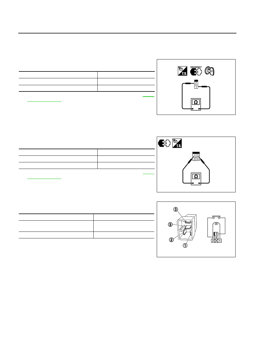
ICC BRAKE SWITCH
1.
Turn ignition switch OFF.
2.
Disconnect ICC brake switch harness connector.
3.
Check continuity between ICC brake switch terminals 1 and 2
under the following conditions.
4.
If NG, adjust ICC brake switch installation, refer to
, and perform step 3 again.
STOP LAMP SWITCH
1.
Turn ignition switch OFF.
2.
Disconnect stop lamp switch harness connector.
3.
Check continuity between stop lamp switch terminals 1 and 2
under the following conditions.
4.
If NG, adjust stop lamp switch installation, refer to
, and perform step 3 again.
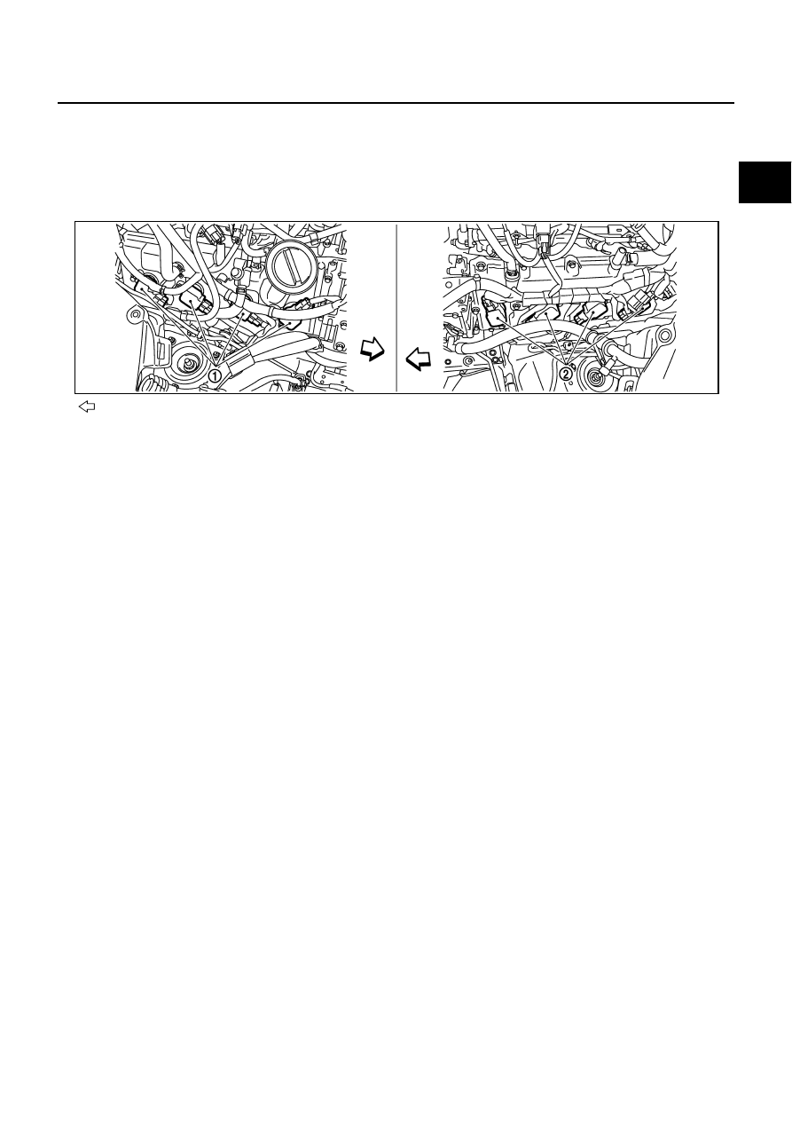
ICC BRAKE HOLD RELAY
1.
Check continuity between ICC brake hold relay terminals 3 and
5 under the following conditions.
2.
If NG, replace ICC brake hold relay.
Condition
Continuity
Brake pedal: Fully released
Should exist
Brake pedal: Slightly depressed
Should not exist
PBIB1536E
Condition
Continuity
Brake pedal: Fully released
Should not exist
Brake pedal: Slightly depressed
Should exist
PBIA9489J
Condition
Continuity
12V direct current supply between terminals
1 and 2
Should not exist
No current supply
Should exist
PBIB0098E
IGNITION SIGNAL
EC-1411
[VK45DE]
C
D
E
F
G
H
I
J
K
L
M
A
EC
IGNITION SIGNAL
PFP:22448
Component Description
NBS005PQ
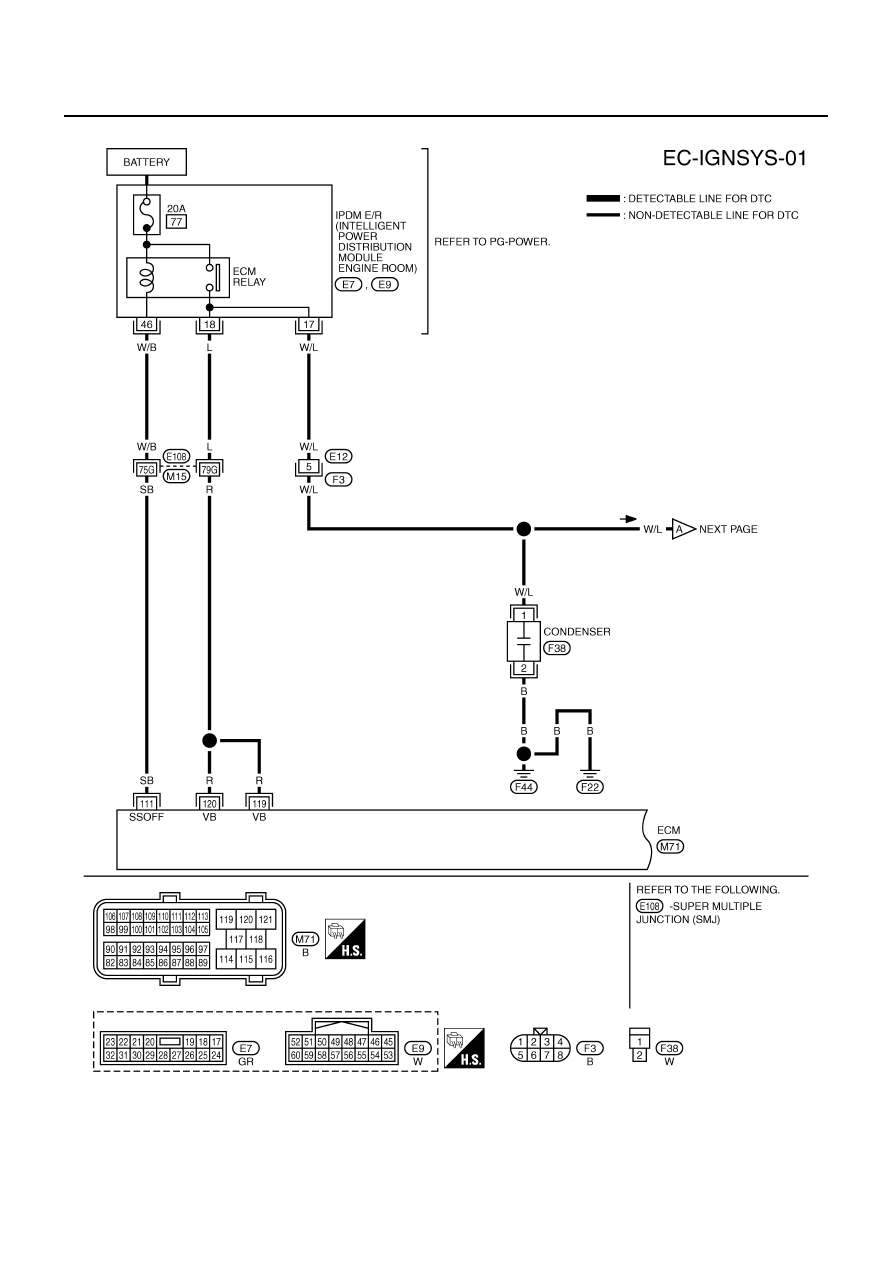
IGNITION COIL & POWER TRANSISTOR
The ignition signal from the ECM is sent to and amplified by the power transistor. The power transistor turns
ON and OFF the ignition coil primary circuit. This ON/OFF operation induces the proper high voltage in the coil
secondary circuit.
: Vehicle front
1.
Ignition coil (with power transistor)
(bank 2)
2.
Ignition coil (with power transistor)
(bank 1)
PBIB2692E
EC-1412
[VK45DE]
IGNITION SIGNAL
Wiring Diagram
NBS005PR
TBWT1061E
Нет комментариевНе стесняйтесь поделиться с нами вашим ценным мнением.
Текст