Infiniti M35/M45 Y50. Manual — part 680
DTC P0643 SENSOR POWER SUPPLY
EC-1193
[VK45DE]
C
D
E
F
G
H
I
J
K
L
M
A
EC
DTC P0643 SENSOR POWER SUPPLY
PFP:18919
On Board Diagnosis Logic
NBS005JY
This self-diagnosis has the one trip detection logic.
FAIL-SAFE MODE
When the malfunction is detected, ECM enters fail-safe mode and the MIL lights up.
DTC Confirmation Procedure
NBS005JZ
NOTE:
If DTC Confirmation Procedure has been previously conducted, always turn ignition switch OFF and wait at
least 10 seconds before conducting the next test.
TESTING CONDITION:
Before performing the following procedure, confirm that battery voltage is more than 10V at idle.
WITH CONSULT-II
1.
Turn ignition switch ON.
2.
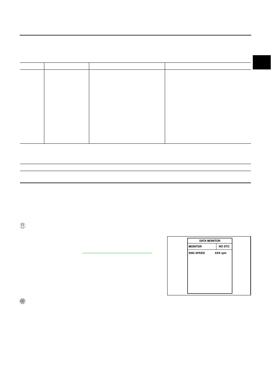
Select “DATA MONITOR” mode with CONSULT-II.
3.
Start engine and let it idle for 1 second.
4.
EC-1196, "Diagnostic Procedure"
.
WITH GST
Follow the procedure “WITH CONSULT-II” above.
DTC No.
Trouble diagnosis name
DTC detecting condition
Possible cause
P0643
0643
Sensor power supply
circuit short
ECM detects a voltage of power source
for sensor is excessively low or high.
●
Harness or connectors
(APP sensor 1 circuit is shorted.)
(EVAP control system pressure sensor is
shorted.)
(Refrigerant pressure sensor circuit is
shorted.)
(PSP sensor circuit is shorted.)
(Battery current sensor circuit is shorted.)
●
Accelerator pedal position sensor
●
EVAP control system pressure sensor
●
Refrigerant pressure sensor
●
Power steering pressure sensor
●
Battery current sensor
Engine operation condition in fail-safe mode
ECM stops the electric throttle control actuator control, throttle valve is maintained at a fixed opening (approx. 5 degrees) by the return
spring.
SEF058Y
EC-1194
[VK45DE]
DTC P0643 SENSOR POWER SUPPLY
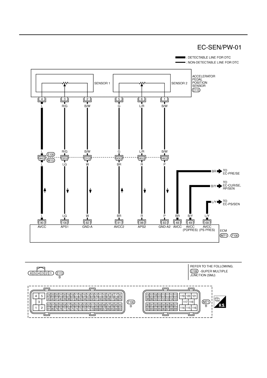
Wiring Diagram
NBS005K0
TBWT1496E

DTC P0643 SENSOR POWER SUPPLY
EC-1195
[VK45DE]
C
D
E
F
G
H
I
J
K
L
M
A
EC
Specification data are reference values and are measured between each terminal and ground.
CAUTION:
Do not use ECM ground terminals when measuring input/output voltage. Doing so may result in dam-
age to the ECM's transistor. Use a ground other than ECM terminals, such as the ground.
TER-
MINAL
NO.
WIRE
COLOR
ITEM
CONDITION
DATA (DC Voltage)
48
BR
Sensor power supply
(EVAP control system pres-
sure sensor)
[Ignition switch: ON]
Approximately 5V
49
B/Y
Sensor power supply
(Refrigerant pressure sen-
sor, Battery current sensor)
[Ignition switch: ON]
Approximately 5V
68
L/Y
Sensor power supply
(Power steering pressure
sensor)
[Ignition switch: ON]
Approximately 5V
82
W
Sensor ground
(APP sensor 1)
[Engine is running]
●
Warm-up condition
●
Idle speed
Approximately 0V
83
P
Sensor ground
(APP sensor 2)
[Engine is running]
●
Warm-up condition
●
Idle speed
Approximately 0V
90
L
Sensor power supply
(APP sensor 1)
[Ignition switch: ON]
Approximately 5V
91
BR
Sensor power supply
(APP sensor 2)
[Ignition switch: ON]
Approximately 5V
98
R
Accelerator pedal position
sensor 2
[Ignition switch: ON]
●
Engine stopped
●
Accelerator pedal: Fully released
0.20 - 0.55V
[Ignition switch: ON]
●
Engine: Stopped
●
Accelerator pedal: Fully depressed
1.85 - 2.40V
106
LG
Accelerator pedal position
sensor 1
[Ignition switch: ON]
●
Engine: Stopped
●
Accelerator pedal: Fully released
0.4 - 1.1V
[Ignition switch: ON]
●
Engine: Stopped
●
Accelerator pedal: Fully depressed
3.7 - 4.8V
EC-1196
[VK45DE]
DTC P0643 SENSOR POWER SUPPLY
Diagnostic Procedure
NBS005K1
1.
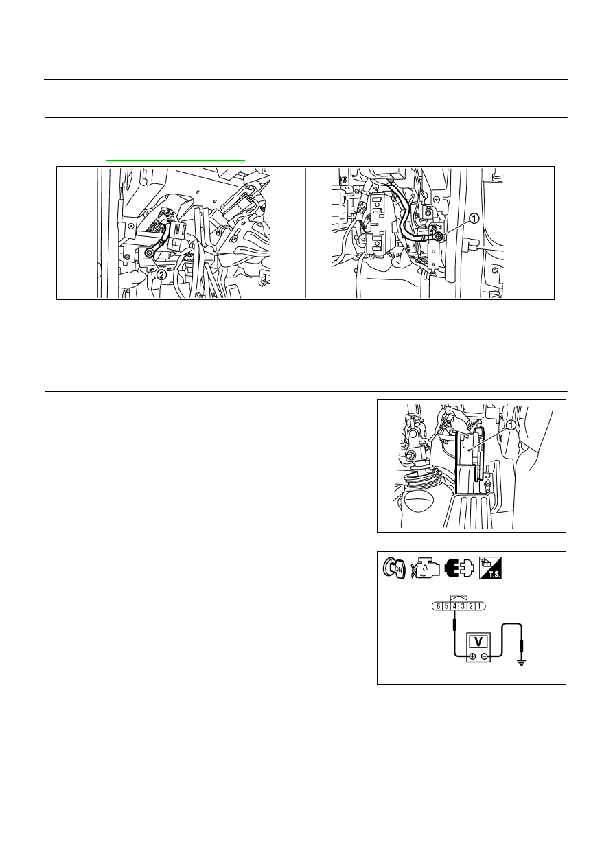
CHECK GROUND CONNECTIONS
1.
Turn ignition switch OFF.
2.
Loosen and retighten ground screws on the body.
Refer to
OK or NG
OK
>> GO TO 2.
NG
>> Repair or replace ground connections.
2.
CHECK ACCELERATOR PEDAL POSITION SENSOR 1 POWER SUPPLY CIRCUIT
1.
Disconnect accelerator pedal position (APP) sensor (1) harness
connector.
2.
Turn ignition switch ON.
3.
Check voltage between APP sensor terminal 4 and ground with
CONSULT-II or tester.
OK or NG
OK
>> GO TO 5.
NG
>> GO TO 3.
1.
Body ground M70
2.
Body ground M16
PBIB2782E
PBIB2704E
Voltage: Approximately 5V
PBIA9606J
Нет комментариевНе стесняйтесь поделиться с нами вашим ценным мнением.
Текст