Infiniti M35/M45 Y50. Manual — part 416
TROUBLE DIAGNOSIS
EC-137
[VQ35DE]
C
D
E
F
G
H
I
J
K
L
M
A
EC
3.
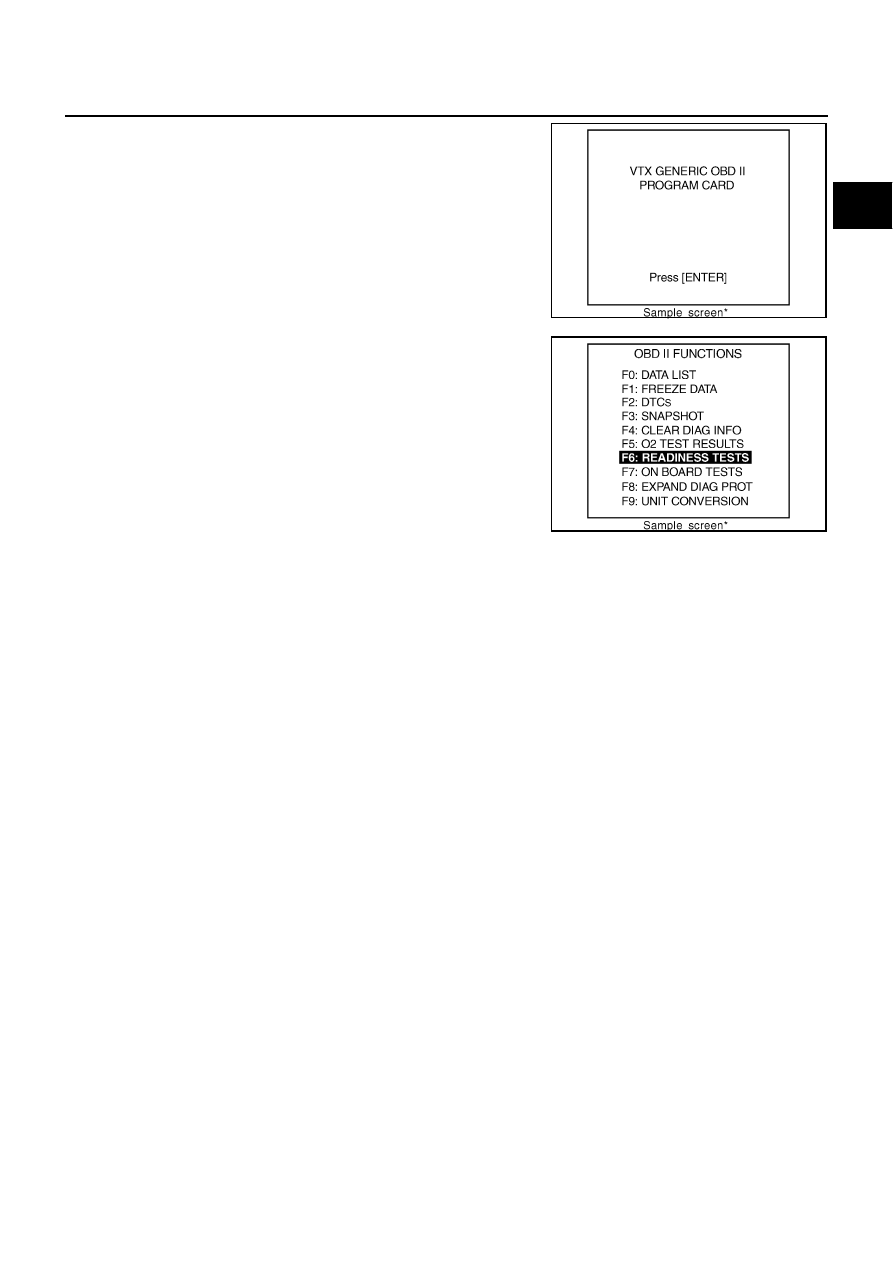
Turn ignition switch ON.
4.
Enter the program according to instruction on the screen or in
the operation manual.
(*: Regarding GST screens in this section, sample screens are
shown.)
5.
Perform each diagnostic mode according to each service proce-
dure.
For further information, see the GST Operation Manual of
the tool maker.
SEF398S
SEF416S

EC-138
[VQ35DE]
TROUBLE DIAGNOSIS
CONSULT-II Reference Value in Data Monitor
NBS004T9
Remarks:
●
Specification data are reference values.
●
Specification data are output/input values which are detected or supplied by the ECM at the connector.
* Specification data may not be directly related to their components signals/values/operations.
i.e. Adjust ignition timing with a timing light before monitoring IGN TIMING, because the monitor may show the specification data in
spite of the ignition timing not being adjusted to the specification data. This IGN TIMING monitors the data calculated by the ECM
according to the signals input from the camshaft position sensor and other ignition timing related sensors.
MONITOR ITEM
CONDITION
SPECIFICATION
ENG SPEED
●
Run engine and compare CONSULT-II value with the tachometer indication.
Almost the same speed as
the tachometer indication.
MAS A/F SE-B1
See
EC-143, "TROUBLE DIAGNOSIS - SPECIFICATION VALUE"
B/FUEL SCHDL
See
EC-143, "TROUBLE DIAGNOSIS - SPECIFICATION VALUE"
A/F ALPHA-B1
A/F ALPHA-B2
See
EC-143, "TROUBLE DIAGNOSIS - SPECIFICATION VALUE"
COOLAN TEMP/S
●
Engine: After warming up
More than 70
°
C (158
°
F)
A/F SEN1 (B1)
A/F SEN1 (B2)
●
Engine: After warming up
Maintaining engine speed at 2,000 rpm
Fluctuates around 1.5 V
HO2S2 (B1)
HO2S2 (B2)
●
Revving engine from idle to 3,000 rpm quickly after the following conditions
are met
–
Engine: After warming up
–
Keeping engine speed between 3,500 and 4,000 rpm for 1 minute and at idle
for 1 minute under no load
0 - 0.3V
←→
Approx. 0.6 -
1.0V
HO2S2 MNTR (B1)
HO2S2 MNTR (B2)
LEAN
←→
RICH
VHCL SPEED SE
●
Turn drive wheels and compare CONSULT-II value with the speedometer
indication.
Almost the same speed as
speedometer indication
BATTERY VOLT
●
Ignition switch: ON (Engine stopped)
11 - 14V
ACCEL SEN 1
ACCEL SEN 2*
1
●
Ignition switch: ON
(Engine stopped)
Accelerator pedal: Fully released
0.4 - 1.1V
Accelerator pedal: Fully depressed
3.7 - 4.8V
THRTL SEN 1
THRTL SEN 2*
1
●
Ignition switch: ON
(Engine stopped)
●
Selector lever: D
Accelerator pedal: Fully released
More than 0.36V
Accelerator pedal: Fully depressed
Less than 4.75V
EVAP SYS PRES
●
Ignition switch: ON
Approx. 1.8 - 4.8V
START SIGNAL
●
Ignition switch: ON
→
START
→
ON
OFF
→
ON
→
OFF
CLSD THL POS
●
Ignition switch: ON
(Engine stopped)
Accelerator pedal: Fully released
ON
Accelerator pedal: Slightly depressed
OFF
AIR COND SIG
●
Engine: After warming up, idle
the engine
Air conditioner switch: OFF
OFF
Air conditioner switch: ON
(Compressor operates.)
ON
P/N POSI SW
●
Ignition switch: ON
Selector lever: P or N
ON
Selector lever: Except above
OFF
PW/ST SIGNAL
●
Engine: After warming up, idle
the engine
Steering wheel: Not being turned
OFF
Steering wheel: Being turned
ON
LOAD SIGNAL
●
Ignition switch: ON
Rear window defogger switch: ON
and/or
Lighting switch: 2nd position
ON
Rear window defogger switch and light-
ing switch: OFF
OFF
IGNITION SW
●
Ignition switch: ON
→
OFF
→
ON
ON
→
OFF
→
ON
HEATER FAN SW
●
Engine: After warming up, idle
the engine
Heater fan switch: ON
ON
Heater fan switch: OFF
OFF
BRAKE SW
●
Ignition switch: ON
Brake pedal: Fully released
OFF
Brake pedal: Slightly depressed
ON

TROUBLE DIAGNOSIS
EC-139
[VQ35DE]
C
D
E
F
G
H
I
J
K
L
M
A
EC
INJ PULSE-B1
INJ PULSE-B2
●
Engine: After warming up
●
Selector lever: P or N
●
Air conditioner switch: OFF
●
No load
Idle
2.0 - 3.0 msec
2,000 rpm
1.9 - 2.9 msec
IGN TIMING
●
Engine: After warming up
●
Selector lever: P or N
●
Air conditioner switch: OFF
●
No load
Idle
13
°
- 18
°
BTDC
2,000 rpm
25
°
- 45
°
BTDC
CAL/LD VALUE
●
Engine: After warming up
●
Selector lever: P or N
●
Air conditioner switch: OFF
●
No load
Idle
5% - 35%
2,500 rpm
5% - 35%
MASS AIRFLOW
●
Engine: After warming up
●
Selector lever: P or N
●
Air conditioner switch: OFF
●
No load
Idle
2.0 - 6.0 g·m/s
2,500 rpm
7.0 - 20.0 g·m/s
PURG VOL C/V
●
Engine: After warming up
●
Selector lever: P or N
●
Air conditioner switch: OFF
●
No load
Idle
(Accelerator pedal: Not depressed even
slightly, after engine starting.)
0%
2,000 rpm
—
INT/V TIM (B1)
INT/V TIM (B2)
●
Engine: After warming up
●
Selector lever: P or N
●
Air conditioner switch: OFF
●
No load
Idle
−
5
°
- 5
°
CA
When revving engine up to 2,000 rpm
quickly
Approx. 0
°
- 30
°
CA
INT/V SOL (B1)
INT/V SOL (B2)
●
Engine: After warming up
●
Selector lever: P or N
●
Air conditioner switch: OFF
●
No load
Idle
0% - 2%
When revving engine up to 2,000 rpm
quickly
Approx. 0% - 50%
AIR COND RLY
●
Engine: After warming up, idle
the engine
Air conditioner switch: OFF
OFF
Air conditioner switch: ON
(Compressor operates)
ON
FUEL PUMP RLY
●
For 1 seconds after turning ignition switch: ON
●
Engine running or cranking
ON
●
Except above
OFF
FPCM
●
Engine: Cranking
HI
●
Engine: Idle
●
Engine coolant temperature: More than 10
°
C (50
°
F)
LOW
VENT CONT/V
●
Ignition switch: ON
OFF
THRTL RELAY
●
Ignition switch: ON
ON
HO2S2 HTR (B1)
HO2S2 HTR (B2)
●
Engine speed: Below 3,600 rpm after the following conditions are met.
–
Engine: After warming up
–
Keeping the engine speed between 3,500 and 4,000 rpm for 1 minute and at
idle for 1 minute under no load
ON
●
Engine speed: Above 3,600 rpm
OFF
I/P PULLY SPD
●
Vehicle speed: More than 20 km/h (12 MPH)
Almost the same speed as
the tachometer indication
VEHICLE SPEED
●
Turn drive wheels and compare CONSULT-II value with the speedometer
indication.
Almost the same speed as
the speedometer indication
MONITOR ITEM
CONDITION
SPECIFICATION

EC-140
[VQ35DE]
TROUBLE DIAGNOSIS
*1: Accelerator pedal position sensor 2 signal and throttle position sensor 2 signal are converted by ECM internally. Thus, they differ
from ECM terminals voltage signal.
*2: Before measuring the terminal voltage, confirm that the battery is fully charged. Refer to
SC-5, "SPECIFIC GRAVITY CHECK"
TRVL AFTER MIL
●
Ignition switch: ON
Vehicle has traveled after MIL has turned
ON.
0 - 65,535 km
(0 - 40,723 miles)
A/F S1 HTR (B1)
A/F S1 HTR (B2)
●
Engine: After warming up, idle the engine
0 - 100%
AC PRESS SEN
●
Engine: Idle
●
Both A/C switch and blower fan switch: ON (Compressor operates)
1.0 - 4.0V
VHCL SPEED SE
●
Turn drive wheels and compare CONSULT-II value with the speedometer
indication.
Almost the same speed as
the speedometer indication
SET VHCL SPD
●
Engine: Running
ASCD: Operating
The preset vehicle speed is
displayed
MAIN SW
●
Ignition switch: ON
MAIN switch: Pressed
ON
MAIN switch: Released
OFF
CANCEL SW
●
Ignition switch: ON
CANCEL switch: Pressed
ON
CANCEL switch: Released
OFF
RESUME/ACC SW
●
Ignition switch: ON
RESUME/ACCELERATE switch:
Pressed
ON
RESUME/ACCELERATE switch:
Released
OFF
SET SW
●
Ignition switch: ON
SET/COAST switch: Pressed
ON
SET/COAST switch: Released
OFF
BRAKE SW1
(ICC/ASCD brake
switch)
●
Ignition switch: ON
Brake pedal: Fully released
ON
Brake pedal: Slightly depressed
OFF
BRAKE SW2
(Stop lamp switch)
●
Ignition switch: ON
Brake pedal: Fully released
OFF
Brake pedal: Slightly depressed
ON
DIST SW
●
Ignition switch: ON
DISTANCE switch: Pressed
ON
DISTANCE switch: Released
OFF
CRUISE LAMP
●
Ignition switch: ON
MAIN switch: Pressed at the 1st time
→
at the 2nd time
ON
→
OFF
SET LAMP
●
MAIN switch: ON
●
When vehicle speed: Between 40
km/h (25 MPH) and 144 km/h (89
MPH)
ASCD: Operating
ON
ASCD: Not operating
OFF
FAN DUTY
●
Engine: Running
0 - 100%
AC EVA TEMP
●
Engine: Idle
●
Both A/C switch and blower fan switch: ON (Compressor operates)
AC EVA TARGET
●
Engine: Idle
●
Both A/C switch and blower fan switch: ON (Compressor operates)
ALT DUTY
●
Engine: Idle
0 - 80%
BAT CUR SEN
●
Engine speed: Idle
●
Battery: Fully charged*
2
●
Selector lever: P or N
●
Air conditioner switch: OFF
●
No load
Approx. 2,600 - 3,500mV
ALT DUTY SIG
●
Power generation voltage variable control: Operating
ON
●
Power generation voltage variable control: Not operating
OFF
MONITOR ITEM
CONDITION
SPECIFICATION
Нет комментариевНе стесняйтесь поделиться с нами вашим ценным мнением.
Текст