Infiniti M35/M45 Y50. Manual — part 968
POWER SUPPLY ROUTING CIRCUIT
PG-17
C
D
E
F
G
H
I
J
L
M
A
B
PG
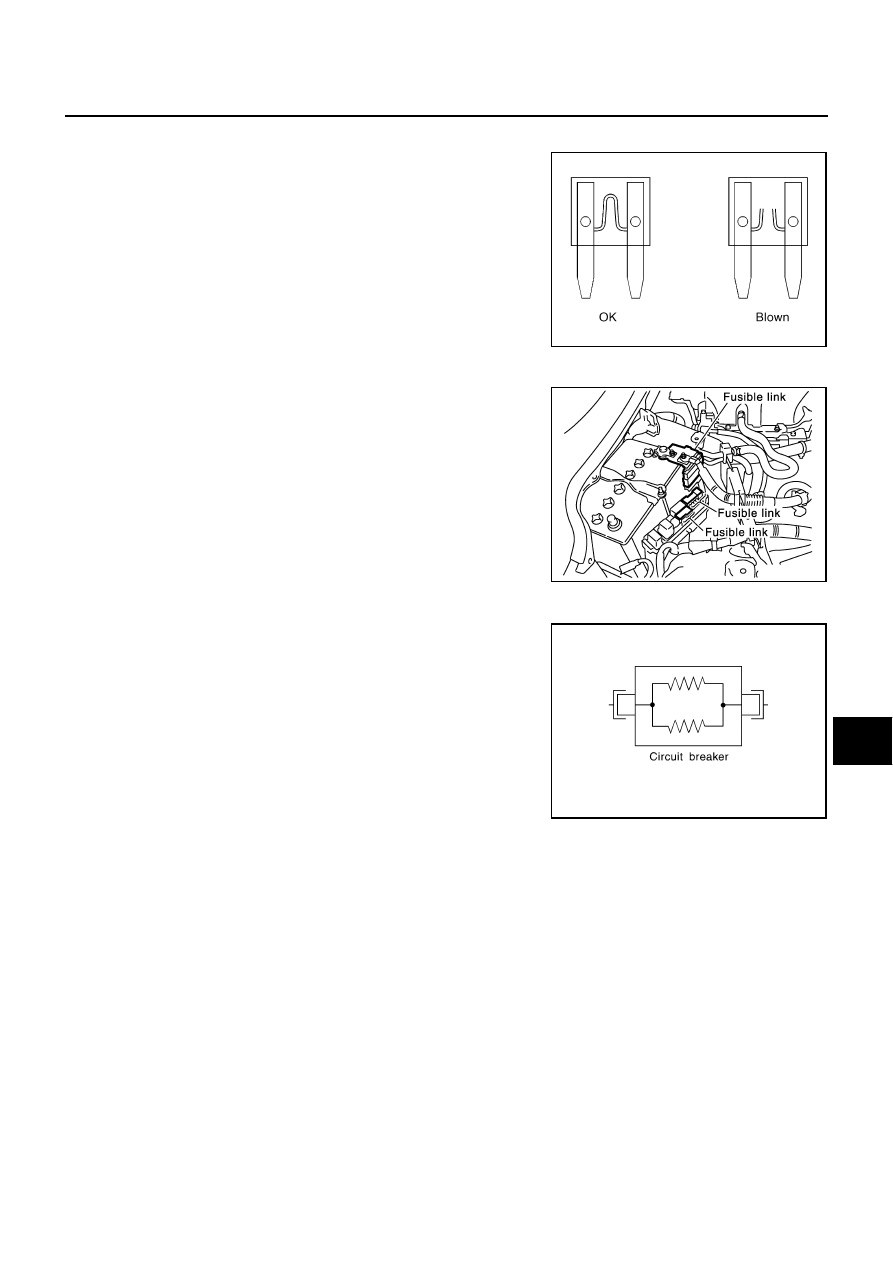
Fuse
NKS004DZ
●
If fuse is blown, be sure to eliminate cause of malfunction before
installing new fuse.
●
Use fuse of specified rating. Never use fuse of more than speci-
fied rating.
●
Do not partially install fuse; always insert it into fuse holder prop-
erly.
●
Remove fuse for “ELECTRICAL PARTS (BAT)” if vehicle is not
used for a long period of time.
Fusible Link
NKS004E0
A melted fusible link can be detected either by visual inspection or by
feeling with finger tip. If its condition is questionable, use circuit
tester or test lamp.
CAUTION:
●
If fusible link should melt, it is possible that critical circuit
(power supply or large current carrying circuit) is shorted.
In such a case, carefully check and eliminate cause of mal-
function.
●
Never wrap outside of fusible link with vinyl tape. Important:
Never let fusible link touch any other wiring harness, vinyl
or rubber parts.
Circuit Breaker
NKS004E1
The PTC thermistor generates heat in response to current flow. The
temperature (and resistance) of the thermistor element varies with
current flow. Excessive current flow will cause the element's temper-
ature to rise. When the temperature reaches a specified level, the
electrical resistance will rise sharply to control the circuit current.
Reduced current flow will cause the element to cool. Resistance falls
accordingly and normal circuit current flow is allowed to resume.
CEL083
CKIT0163E
SEL109W

PG-18
IPDM E/R (INTELLIGENT POWER DISTRIBUTION MODULE ENGINE ROOM)
IPDM E/R (INTELLIGENT POWER DISTRIBUTION MODULE ENGINE ROOM)
PFP:284B7
System Description
NKS004E2
●
IPDM E/R (Intelligent Power Distribution Module Engine Room) integrates the relay box and fuse block
which were originally placed in engine compartment. It controls integrated relay via IPDM E/R control cir-
cuit.
●
IPDM E/R-integrated control circuit performs ON-OFF operation of relay, CAN communication control and
oil pressure switch signal reception, etc.
●
It controls operation of each electrical part via ECM, BCM and CAN communication lines.
CAUTION:
None of the IPDM E/R-integrated relays can be removed.
SYSTEMS CONTROLLED BY IPDM E/R
1.
Lamp control
Using CAN communication, it receives signal from BCM and controls the following lamps:
●
Headlamps (HI, LO)
●
Tail, parking and license plate lamps
●
Front fog lamps
2.
Daytime light relay control (for Canada models)
Using CAN communication, it receives signals from BCM and controls the daytime light relay.
3.
Wiper control
Using CAN communication, it receives signals from BCM and controls the front wipers.
4.
Rear window defogger relay control
Using CAN communication, it receives signals from BCM and controls the rear window defogger relay.
5.
A/C compressor control
Using CAN communication, it receives signals from ECM and controls the A/C relay.
6.
Cooling fan control
Using CAN communication, it receives signals from ECM and controls cooling fan via cooling fan control
module.
7.
Horn control
Using CAN communication, it receives signals from BCM and controls horn relay.
8.
Starter motor relay control
Using CAN communication, it receives signals from BCM and controls starter motor relay.
9.
Alternator control
Using CAN communication, it receives signal from ECM and controls power generation voltage.
CAN COMMUNICATION LINE CONTROL
With CAN communication, by connecting each control unit using two communication lines (CAN L-line, CAN
H-line), it is possible to transmit maximum amount of information with minimum wiring. Each control unit can
transmit and receive data, and reads necessary information only.
1.
Fail-safe control
●
When CAN communication with other control units is impossible, IPDM E/R performs fail-safe control.
After CAN communication recovers normally, it also returns to normal control.
●
Operation of control parts by IPDM E/R during fail-safe mode is as follows:
Controlled system
Fail-safe mode
Headlamps
●
With the ignition switch ON, the headlamp low relay is ON.
●
With the ignition switch OFF, the headlamp low relay is OFF.
Tail, parking and
license plate lamps
●
With the ignition switch ON, the tail lamp relay is ON.
●
With the ignition switch OFF, the tail lamp relay is OFF.
Cooling fan
●
With the ignition switch ON, the cooling fan HI operates.
●
With the ignition switch OFF, the cooling fan stops.
Front wiper
Until the ignition switch is turned off, the front wiper LO and HI remains in the same status it was in just
before fail
−
safe control was initiated.

IPDM E/R (INTELLIGENT POWER DISTRIBUTION MODULE ENGINE ROOM)
PG-19
C
D
E
F
G
H
I
J
L
M
A
B
PG
IPDM E/R STATUS CONTROL
In order to save power, IPDM E/R switches status by itself based on each operating condition.
1.
CAN communication status
●
CAN communication is normally performed with other control units.
●
Individual unit control by IPDM E/R is normally performed.
●
When sleep request signal is received from BCM, mode is switched to sleep transient status.
2.
Sleep transient status
●
Process to stop CAN communication is activated.
●
All systems controlled by IPDM E/R are stopped. When 3 seconds have elapsed after CAN communi-
cation with other control units is stopped, mode switches to sleep status.
3.
Sleep status
●
IPDM E/R operates in low power mode.
●
CAN communication is stopped.
●
When a change in CAN communication line is detected, mode switches to CAN communication status.
●
When a change hood switch or ignition switch signal is detected, mode switches to CAN communica-
tion status.
CAN Communication System Description
NKS004E3
CAN (Controller Area Network) is a serial communication line for real time application. It is an on-vehicle mul-
tiplex communication line with high data communication speed and excellent error detection ability. Modern
vehicles are equipped with many electronic control units and each control unit shares information and links
with other control units during operation (not independent). In CAN communication, control units are con-
nected with 2 communication lines (CAN H line, CAN L line) allowing a high rate of information transmission
with less wiring. Each control unit transmits/receives data but selectively reads required data only.
CAN Communication Unit
NKS004E4
Refer to
LAN-50, "CAN System Specification Chart"
.
Function of Detecting Ignition Relay Malfunction
NKS004E5
●
When contact point of integrated ignition relay is stuck and cannot be turned OFF, IPDM E/R turns ON tail
and parking lamps for 10 minutes to indicate ignition relay malfunction.
●
When a state of ignition relay having built-in does not agree with a state of Ignition switch signal input by a
CAN communication from BCM, IPDM E/R lets tail lamp relay operate.
NOTE:
When the ignition switch is turned ON, the tail lamps are OFF.
Rear window defogger
Rear window defogger relay OFF
A/C compressor
A/C relay OFF
Front fog lamps
Front fog lamp relay OFF
Controlled system
Fail-safe mode
Ignition switch signal
Ignition relay status
Tail lamp relay
ON
ON
—
OFF
OFF
—
ON
OFF
—
OFF
ON
ON (10 minutes)

PG-20
IPDM E/R (INTELLIGENT POWER DISTRIBUTION MODULE ENGINE ROOM)
CONSULT-II Function (IPDM E/R)
NKS004E6
CONSULT-II can display each diagnostic item using the diagnostic test modes shown following.
CONSULT-II BASIC OPERATION
Refer to
GI-38, "CONSULT-II Start Procedure"
SELF-DIAG RESULTS
Operation Procedure
1.
Touch “SELF-DIAG RESULTS” on “SELECT DIAG MODE” screen.
2.
Check display content in self-diagnostic results.
Display Item List
NOTE:
The details for display of the period are as follows:
●
CRNT: Error currently detected with IPDM E/R.
●
PAST: Error detected in the past and memorized with IPDM E/R.
Inspection Item, Diagnosis Mode
Description
SELF-DIAG RESULTS
The IPDM E/R performs diagnosis of the CAN communication and self-diagnosis.
DATA MONITOR
The input/output data of the IPDM E/R is displayed in real time.
CAN DIAG SUPPORT MNTR
The result of transmit/receive diagnosis of CAN communication can be read.
ACTIVE TEST
The IPDM E/R sends a drive signal to electronic components to check their operation.
Display Items
CONSULT-II
display code
Malfunction detecting condition
TIME
Possible causes
CRNT
PAST
NO DTC IS
DETECTED.FURTHER
TESTING MAY BE
REQUIRED.
-
-
-
-
-
CAN COMM CIRC
U1000
●
If CAN communication reception/transmission
data has a malfunction, or if any of the control
units malfunction, data reception/transmission
cannot be confirmed.
●
When the data in CAN communication is not
received before the specified time
×
×
Any of or several items
below have errors.
●
TRANSMIT DIAG
●
ECM
●
BCM/SEC
Нет комментариевНе стесняйтесь поделиться с нами вашим ценным мнением.
Текст