Infiniti M35/M45 Y50. Manual — part 510
DTC P1220 FUEL PUMP CONTROL MODULE (FPCM)
EC-513
[VQ35DE]
C
D
E
F
G
H
I
J
K
L
M
A
EC
Specification data are reference values and are measured between each terminal and ground.
CAUTION:
Do not use ECM ground terminals when measuring input/output voltage. Doing so may result in dam-
age to the ECM's transistor. Use a ground other than ECM terminals, such as the ground.
Diagnostic Procedure
NBS0053F
1.
CHECK GROUND CONNECTIONS
1.
Turn ignition switch OFF.
2.
Loosen and retighten two ground screws on the body.
Refer to
OK or NG
OK
>> GO TO 2.
NG
>> Repair or replace ground connections.
TER-
MINAL
NO.
WIRE
COLOR
ITEM
CONDITION
DATA (DC Voltage)
38
G/R
Fuel pump control module
(FPCM) check
[When cranking engine]
Approximately 0V
[Engine is running]
●
Warm-up condition
●
Idle speed
4 - 6V
39
B/R
Fuel pump control module
(FPCM)
[When cranking engine]
0 - 0.5V
[Engine is running]
●
Warm-up condition
●
Idle speed
8 - 12V
113
GR
Fuel pump relay
[Ignition switch: ON]
●
For 1 second after turning ignition switch ON
[Engine is running]
0 - 1.5V
[Ignition switch: ON]
●
More than 1 second after turning ignition
switch ON
BATTERY VOLTAGE
(11 - 14V)
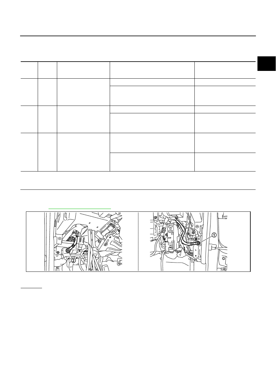
1.
Body ground M70
2.
Body ground M16
PBIB2782E
EC-514
[VQ35DE]
DTC P1220 FUEL PUMP CONTROL MODULE (FPCM)
2.
CHECK FPCM POWER SUPPLY CIRCUIT
1.
Disconnect fuel pump control module (FPCM) harness connector.
2.
Turn ignition switch ON.
3.
Check voltage between FPCM terminal 2 and ground with CON-
SULT-II or tester.
OK or NG
OK
>> GO TO 4.
NG
>> GO TO 3.
3.
DETECT MALFUNCTIONING PART
Check the following.
●
Harness connectors E106, B4
●
Harness for open or short between FPCM and harness connector B4
>> Repair open circuit or short to ground or short to power in harness or connectors.
4.
CHECK FPCM GROUND CIRCUIT-I FOR OPEN AND SHORT
1.
Turn ignition switch OFF.
2.
Check harness continuity between FPCM terminal 3 and ground.
Refer to Wiring Diagram.
3.
Also check harness for short to power.
OK or NG
OK
>> GO TO 5.
NG
>> Repair open circuit or short to power in harness or connectors.
: Vehicle front
1.
FPCM
2.
Dropping resistor
Voltage: Battery voltage
PBIB2708E
PBIB0099E
Continuity should exist.

DTC P1220 FUEL PUMP CONTROL MODULE (FPCM)
EC-515
[VQ35DE]
C
D
E
F
G
H
I
J
K
L
M
A
EC
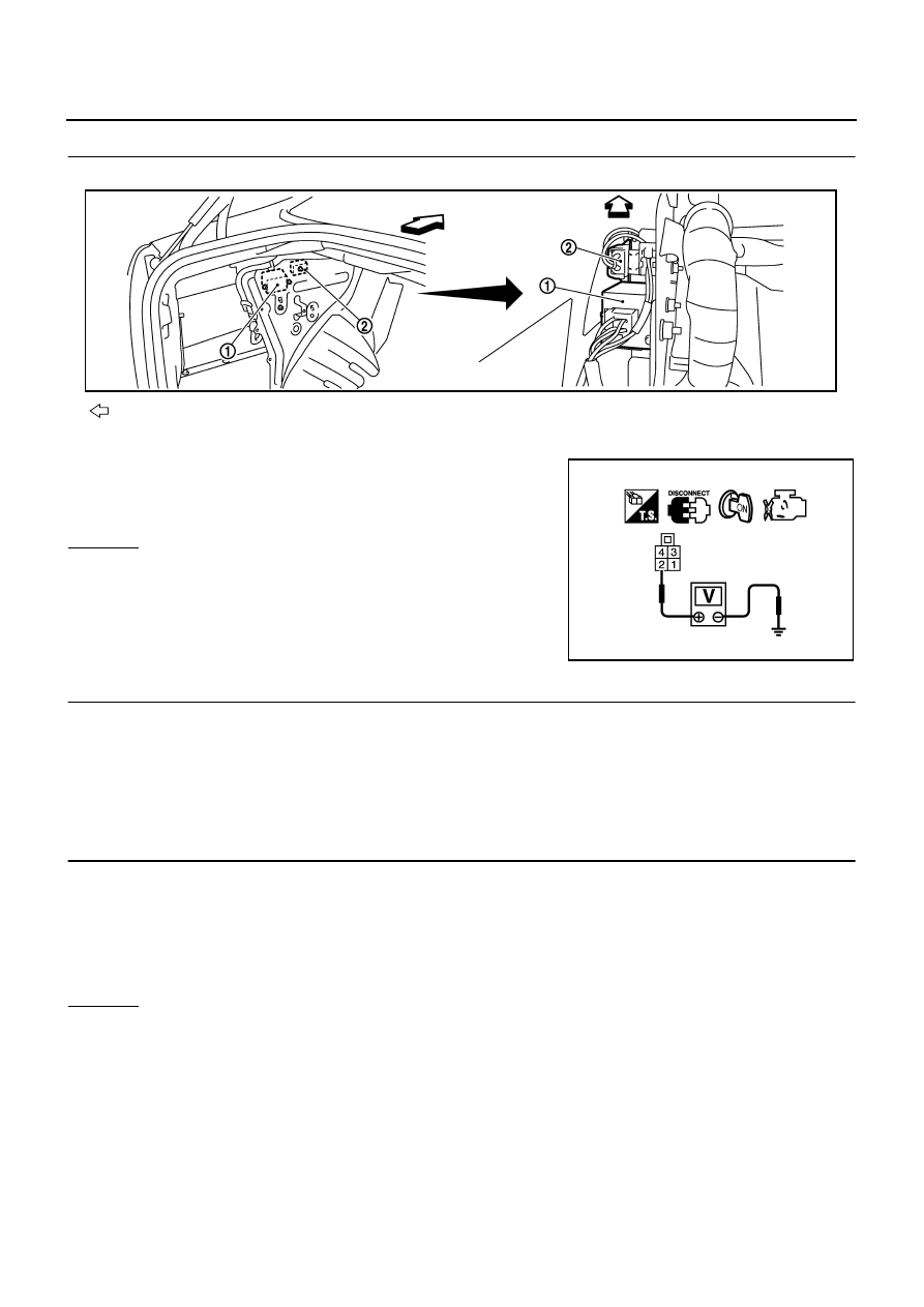
5.
CHECK FPCM GROUND CIRCUIT-II FOR OPEN AND SHORT
1.
Disconnect “fuel level sensor unit and fuel pump” harness con-
nector (1).
–
Illustration shows the view with rear seat cushion and inspection
hole cover (RH) removed.
–
: Vehicle front
2.
Disconnect dropping resistor harness connector.
3.
Check harness continuity between the following;
“fuel level sensor unit and fuel pump” terminal 3 and dropping resistor terminal 2,
FPCM terminal 4 and dropping resister terminal 2.
Refer to Wiring Diagram.
4.
Check harness continuity between the following;
“fuel level sensor unit and fuel pump” terminal 3 and ground,
FPCM terminal 4 and ground.
Refer to Wiring Diagram.
5.
Also check harness for short to power.
OK or NG
OK
>> GO TO 7.
NG
>> GO TO 6.
6.
DETECT MALFUNCTIONING PART
Check the following.
●
Harness connectors B434, B65
●
Harness for open or short between “fuel level sensor unit and fuel pump” and dropping resistor
●
Harness for open or short between FPCM and dropping resistor
●
Harness for open or short between harness connector B65 and ground
●
Harness for open or short between FPCM and ground
>> Repair open circuit or short to ground or short to power in harness or connectors.
PBIB2706E
: Vehicle front
1.
FPCM
2.
Dropping resistor
Continuity should exist.
Continuity should not exist.
PBIB2708E
EC-516
[VQ35DE]
DTC P1220 FUEL PUMP CONTROL MODULE (FPCM)
7.
CHECK FPCM INPUT SIGNAL CIRCUIT FOR OPEN AND SHORT
1.
Disconnect ECM harness connector.
2.
Check harness continuity between ECM terminal 38 and FPCM terminal 4.
Refer to Wiring Diagram.
3.
Check harness continuity between ECM terminal 38 and ground.
Refer to Wiring Diagram.
4.
Also check harness for short to power.
OK or NG
OK
>> GO TO 9.
NG
>> GO TO 8.
8.
DETECT MALFUNCTIONING PART
Check the following.
●
Harness connectors B2, M13
●
Harness connectors M72, F102
●
Harness for open or short between ECM and FPCM
>> Repair open circuit or short to ground or short to power in harness or connectors.
9.
CHECK FPCM OUTPUT SIGNAL CIRCUIT FOR OPEN AND SHORT
1.
Check harness continuity between ECM terminal 39 and FPCM terminal 1.
Refer to Wiring Diagram.
2.
Also check harness for short to ground and short to power.
OK or NG
OK
>> GO TO 11.
NG
>> GO TO 10.
10.
DETECT MALFUNCTIONING PART
Check the following.
●
Harness connectors B2, M13
●
Harness connectors M72, F102
●
Harness for open or short between ECM and FPCM
>> Repair open circuit or short to ground or short to power in harness or connectors.
11.
CHECK FPCM
Refer to
EC-517, "Component Inspection"
OK or NG
OK
>> GO TO 12.
NG
>> Replace FPCM.
Continuity should exist.
Continuity should not exist.
Continuity should exist.
Нет комментариевНе стесняйтесь поделиться с нами вашим ценным мнением.
Текст