Infiniti M35/M45 Y50. Manual — part 848

HOW TO USE THIS SECTION
LAN-41
[CAN]
C
D
E
F
G
H
I
J
L
M
A
B
LAN
HOW TO USE THIS SECTION
PFP:00008
Caution
NKS004FN
●
This section describes information specific to a vehicle, sheets for trouble diagnosis, and inspection pro-
cedures.
●
For trouble diagnosis procedure, refer to
LAN-17, "Trouble Diagnosis Procedure"
.
Abbreviation List
NKS004FO
Abbreviations in CAN communication signal chart and the diagnosis sheet are as per the following list.
Abbreviation
Unit name
SELECT SYSTEM
(CONSULT-II)
CAN DIAG SUPPORT MNTR
(CONSULT-II)
4WD
AWD control unit
ALL MODE AWD/4WD
AWD/4WD
ABS
ABS actuator and electric unit (control unit)
ABS
VDC/TCS/ABS
ADP
Driver seat control unit
AUTO DRIVE POS.
–
AFS
AFS control unit
ADAPTIVE LIGHT
AFS
AV
NAVI control unit
MULTI AV
MULTI AV
DISPLAY
AV control unit
MULTI AV
DISPLAY
BCM
BCM
BCM
BCM/SEC
DLC
Data link connector
–
–
ECM
ECM
ENGINE
ECM
ICC
ICC sensor integrated unit
ICC
ICC
ICC/e4WD
I-KEY
Intelligent Key unit
INTELLIGENT KEY
I-KEY
IPDM-E
IPDM E/R
IPDM E/R
IPDM E/R
M&A
Unified meter and A/C amp.
METER A/C AMP
METER/M&A
PSB
Pre-crash seat belt control unit
PRECRASH SEATBELT
–
RAS
RAS control unit
RAS/HICAS
RAS C/U
STRG
Steering angle sensor
–
STRG
TCM
TCM
A/T
TCM
TPMS
Low tire pressure warning control unit
AIR PRESSURE MONITOR
TIRE-P
LANE
LDW camera unit
LDW
–
LAN-42
[CAN]
PRECAUTIONS
PRECAUTIONS
PFP:00001
Precautions for Supplemental Restraint System (SRS) “AIR BAG” and “SEAT
BELT PRE-TENSIONER”
NKS004HN
The Supplemental Restraint System such as “AIR BAG” and “SEAT BELT PRE-TENSIONER”, used along
with a front seat belt, helps to reduce the risk or severity of injury to the driver and front passenger for certain
types of collision. This system includes seat belt switch inputs and dual stage front air bag modules. The SRS
system uses the seat belt switches to determine the front air bag deployment, and may only deploy one front
air bag, depending on the severity of a collision and whether the front occupants are belted or unbelted.
Information necessary to service the system safely is included in the SRS and SB section of this Service Man-
ual.
WARNING:
●
To avoid rendering the SRS inoperative, which could increase the risk of personal injury or death
in the event of a collision which would result in air bag inflation, all maintenance must be per-
formed by an authorized NISSAN/INFINITI dealer.
●
Improper maintenance, including incorrect removal and installation of the SRS, can lead to per-
sonal injury caused by unintentional activation of the system. For removal of Spiral Cable and Air
Bag Module, see the SRS section.
●
Do not use electrical test equipment on any circuit related to the SRS unless instructed to in this
Service Manual. SRS wiring harnesses can be identified by yellow and/or orange harnesses or
harness connectors.
Precautions When Using CONSULT-II
NKS004HK
Use CONSULT-II CONVERTER when connecting CONSULT-II to data link connector.
CAUTION:
CAN communication does not function properly if CONSULT-II is used without connecting CONSULT-II
CONVERTER.
Precautions for Trouble Diagnosis
NKS004HL
CAUTION:
●
Never apply 7.0 V or more to the measurement terminal.
●
Use a tester with open terminal voltage of 7.0 V or less.
●
Turn the ignition switch OFF and disconnect the battery cable from the negative terminal when
checking the harness.
Precautions for Harness Repair
NKS004HM
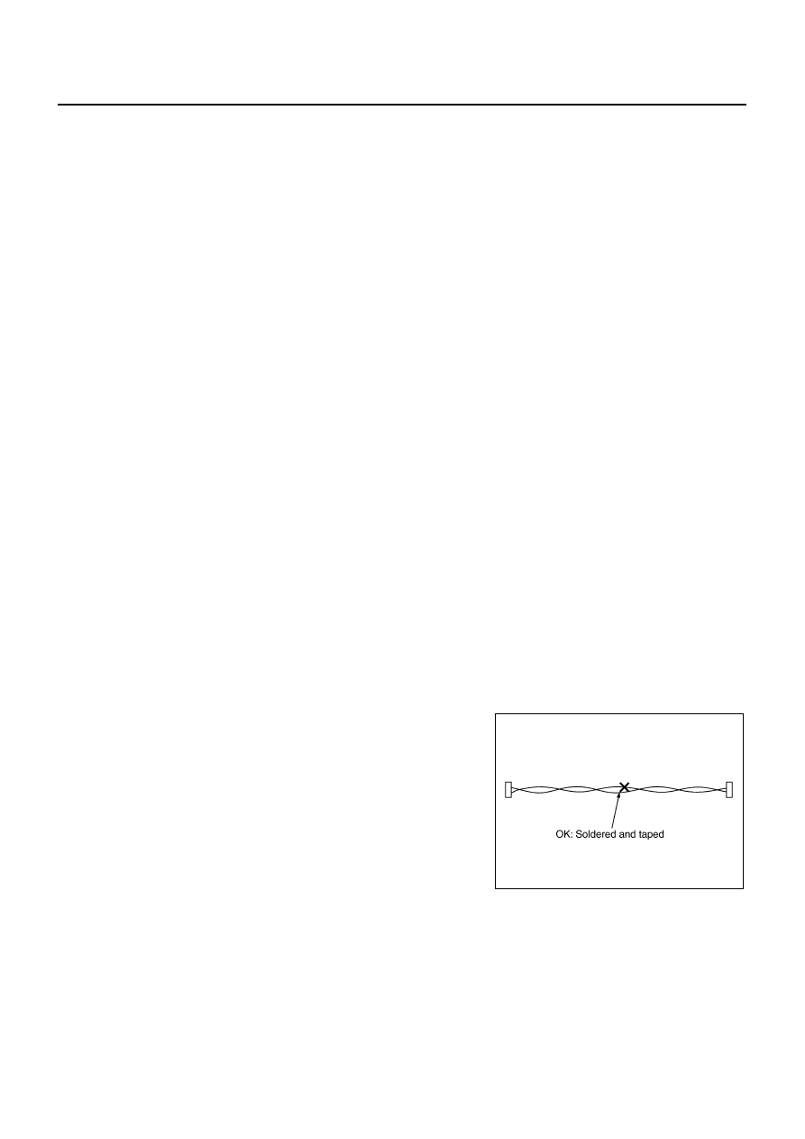
●
Solder the repaired area and wrap tape around the soldered
area.
NOTE:
A fray of twisted lines must be within 110 mm (4.33 in).
SKIB8766E

PRECAUTIONS
LAN-43
[CAN]
C
D
E
F
G
H
I
J
L
M
A
B
LAN
●
Bypass connection is never allowed at the repaired area.
NOTE:
Bypass connection may cause CAN communication error. The
spliced wire becomes separated and the characteristics of
twisted line are lost.
●
Replace the applicable harness as an assembly if error is detected on the shield lines of CAN communi-
cation line.
SKIB8767E

LAN-44
[CAN]
TROUBLE DIAGNOSIS
TROUBLE DIAGNOSIS
PFP:00004
CAN Diagnostic Support Monitor
NKS004FT
Use “CAN DIAG SUPPORT MNTR” for detecting the root cause.
MONITOR ITEM LIST (CONSULT-II)
ECM
0: Error at present, 1 – 39: Error in the past (Number means the number of times the ignition switch is turned OFF
→
ON)
*: 39 or higher number is fixed at 39 until the self-diagnosis result is erased.
AWD control unit
NOTE:
Replace the unit when “NG” is indicated on the “INITIAL DIAG”.
SELECT SYS-
TEM
CAN DIAG SUP-
PORT MNTR
Description
Normal
Error
PRSNT
PAST
PRSNT
PAST
ENGINE
TRANSMIT DIAG
Signal transmission status
OK
OK
or
1 – 39
*
UNKWN
0
VDC/TCS/ABS
Signal receiving status from the ABS actu-
ator and electric unit (control unit)
METER/M&A
Signal receiving status from the unified
meter and A/C amp.
BCM/SEC
Signal receiving status from the BCM
ICC
Signal receiving status from the ICC sen-
sor integrated unit
HVAC
Not used even though indicated
TCM
Signal receiving status from the TCM
OK
OK
or
1 – 39
*
UNKWN
0
EPS
Not used even though indicated
IPDM E/R
Signal receiving status from the IPDM E/R
OK
OK
or
1 – 39
*
UNKWN
0
e4WD
Not used even though indicated
AWD/4WD
Signal receiving status from the AWD con-
trol unit
OK
OK
or
1 – 39
*
UNKWN
0
SELECT SYS-
TEM
CAN DIAG SUP-
PORT MNTR
Description
Normal
Error
PRSNT
ALL MODE AWD/
4WD
INITIAL DIAG
Status of CAN controller
OK
NG
TRANSMIT DIAG
Signal transmission status
UNKWN
VDC/TCS/ABS
Signal receiving status from the ABS actuator and electric unit
(control unit)
ECM
Signal receiving status from the ECM
TCM
Not used even though indicated
METER/M&A
Signal receiving status from the unified meter and A/C amp.
OK
UNKWN
Нет комментариевНе стесняйтесь поделиться с нами вашим ценным мнением.
Текст