
Dodge Ram Truck 1500-2500-3500. Manual — part 1102
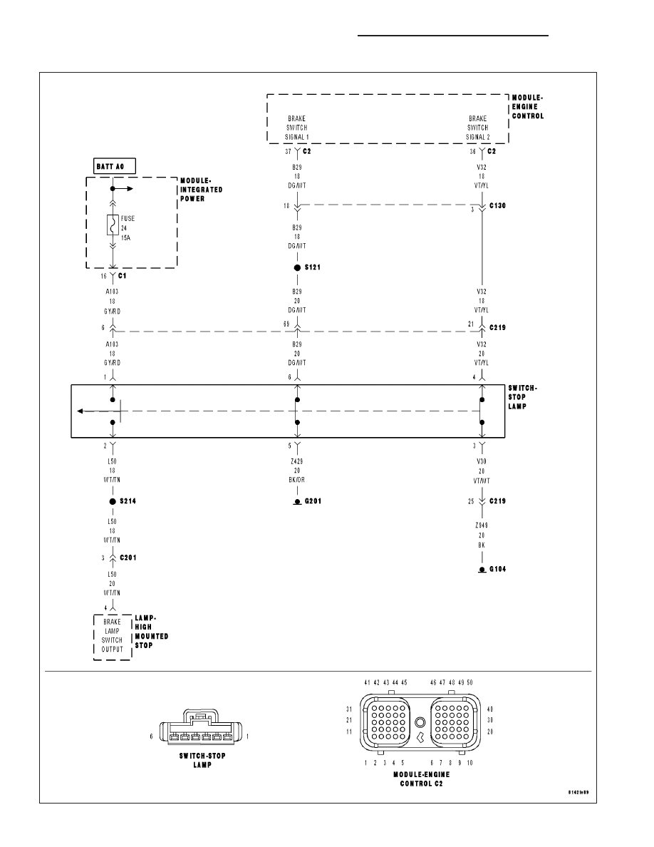
P0573-HIGH VOLTAGE DETECTED AT THE BRAKE SWITCH
9 - 1330
ENGINE - ELECTRICAL DIAGNOSTICS - DIESEL
DR/DH
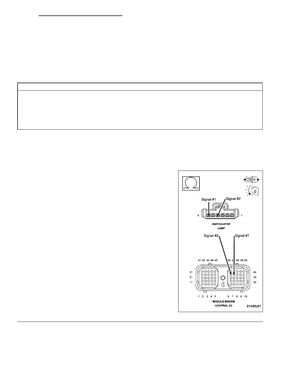
P0573-HIGH VOLTAGE DETECTED AT THE BRAKE SWITCH (CONTINUED)
For the Engine circuit diagram (Refer to 8 - ELECTRICAL/ELECTRONIC CONTROL MODULES/ENGINE CON-
TROL MODULE - SCHEMATIC - ELECTRICAL)
For a complete wiring diagram Refer to Section 8W.
•
When Monitored:
While the ignition is on.
•
Set Condition:
The brake switch status is = to ON and the not brake switch status is = to OFF for a calibrated amount of time.
Possible Causes
DAMAGED WIRING HARNESS OR CONNECTORS
BRAKE SWITCH CIRCUIT OPEN (BRAKE SWITCH WILL ALWAYS BE ON)
BRAKE SWITCH CIRCUIT SHORTED TO BATTERY VOLTAGE (BRAKE SWITCH WILL ALWAYS BE ON)
BRAKE SWITCH
ECM
Always perform the Pre-Diagnostic Troubleshooting procedure before proceeding. (Refer to 9 - ENGINE -
DIAGNOSIS AND TESTING)
1.
BRAKE SWITCH CIRCUIT OPEN
Turn the ignition off.
Disconnect the brake switch connection. Inspect the pins and connec-
tor for damage, corrosion, etc.
Disconnect the ECM connectors. Inspect the pins and connector for
damage, corrosion, etc.
NOTE: Check connectors - Clean/repair as necessary.
Measure the resistance between the brake switch signal circuits in the
ECM connector and the brake switch connector.
Is the resistance less than 10 ohms?
Yes
>> Go To 2
No
>> Repair the open brake switch circuits.
Perform POWERTRAIN VERIFICATION TEST VER - 1
(DIESEL). (Refer to 8 - ELECTRICAL/ELECTRONIC CON-
TROL MODULES/ENGINE CONTROL MODULE - DIAG-
NOSIS AND TESTING)
DR/DH
ENGINE - ELECTRICAL DIAGNOSTICS - DIESEL
9 - 1331
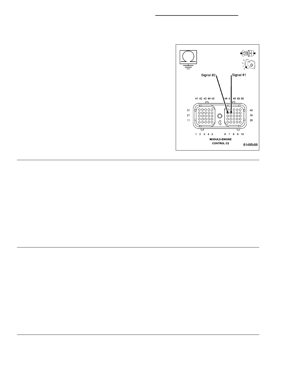
P0573-HIGH VOLTAGE DETECTED AT THE BRAKE SWITCH (CONTINUED)
2.
BRAKE SWITCH CIRCUIT SHORTED TO VOLTAGE
Measure the voltage between the brake switch circuits in the ECM
connector and battery negative.
Is the voltage less than 1 volt?
Yes
>> Go To 3
No
>> Repair the open circuit.
Perform POWERTRAIN VERIFICATION TEST VER - 1
(DIESEL). (Refer to 8 - ELECTRICAL/ELECTRONIC CON-
TROL MODULES/ENGINE CONTROL MODULE - DIAG-
NOSIS AND TESTING)
3.
ECM
Reconnect the ECM connectors.
Install a jumper wire in the brake switch connector between signal circuit and to ground.
Turn the ignition on.
Cycle the brake pedal several times.
Using the scan tool, read the DTC’s.
Is the DTC for brake switch low voltage present?
Yes
>> Go To 4
No
>> Replace the ECM.
Perform POWERTRAIN VERIFICATION TEST VER - 1 (DIESEL). (Refer to 8 - ELECTRICAL/ELEC-
TRONIC CONTROL MODULES/ENGINE CONTROL MODULE - DIAGNOSIS AND TESTING)
4.
BRAKE SWITCH
Reconnect the brake switch connector.
Using the scan tool, clear the DTC’s.
Turn the ignition on.
Cycle the brake pedal several times.
Using the scan tool, read the DTC’s.
Has the brake switch High DTC returned?
Yes
>> Replace the brake switch.
Perform POWERTRAIN VERIFICATION TEST VER - 1 (DIESEL). (Refer to 8 - ELECTRICAL/ELEC-
TRONIC CONTROL MODULES/ENGINE CONTROL MODULE - DIAGNOSIS AND TESTING)
No
>> Perform Intermittent condition test. (Refer to 9 - ENGINE - DIAGNOSIS AND TESTING)
9 - 1332
ENGINE - ELECTRICAL DIAGNOSTICS - DIESEL
DR/DH
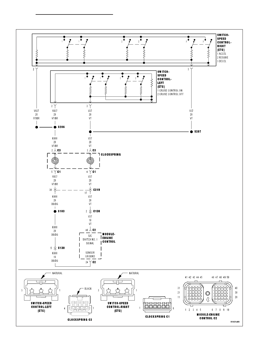
P0580-LOW VOLTAGE DETECTED AT THE SPEED CONTROL SWITCH
DR/DH
ENGINE - ELECTRICAL DIAGNOSTICS - DIESEL
9 - 1333
Нет комментариевНе стесняйтесь поделиться с нами вашим ценным мнением.
Текст