Dodge Dakota (ND). Manual — part 615
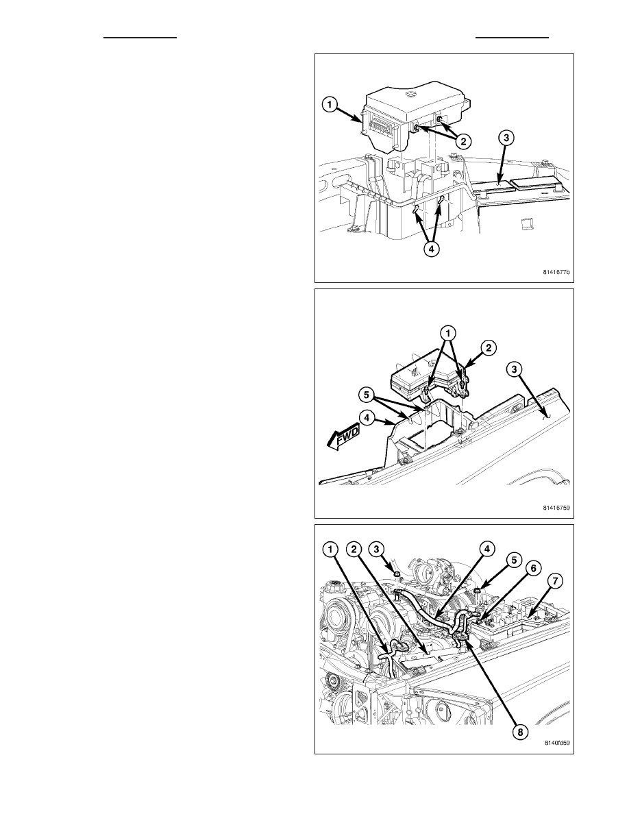
2. Position the Integrated Power Module (IPM) (1) into
the battery tray. Move the IPM down and rearward
to engage the locking tabs (2) into the battery tray
locating slots (4).
3. Install the IPM (2) pushpin fasteners (1) into the
battery tray (4).
4. Position the battery positive cable (4) and install
the nut (5) onto the IPM B+ terminal stud (6).
Install the IPM cover.
5. Connect the battery negative cable.
6. Confirm proper vehicle operation.
8W - 97 - 6
8W-97 POWER DISTRIBUTION - SERVICE INFORMATION
ND
IOD FUSE
DESCRIPTION
All vehicles are equipped with an Ignition-Off Draw (IOD) fuse that is disconnected within the Integrated Power Mod-
ule when the vehicle is shipped from the factory. Dealer personnel are to reconnect the IOD fuse in the Integrated
Power Module as part of the preparation procedures performed just prior to new vehicle delivery. The IOD fuse can
be removed to avoid discharging the battery by disconnecting non-essential, low-current memory functions that are
normally on at all times. A detent on the IOD fuse holder allows it to be stored in its normal cavity but out of contact.
The holder is pushed into place to restore power to the systems it supplies. The following circuits are protected by
the IOD fuse:
•
Cluster (CCN)
•
Diagnostic Connector
•
Map Lamps
•
Glove Box Lamp
•
Courtesy Lamps
•
Radio
•
Underhood Lamp
OPERATION
The term ignition-off draw identifies a normal condition where power is being drained from the battery with the igni-
tion switch in the Off position. The IOD fuse feeds the memory and sleep mode functions for some of the electronic
modules in the vehicle as well as various other accessories that require battery current when the ignition switch is
in the Off position. The only reason the IOD fuse is disconnected is to reduce the normal IOD of the vehicle elec-
trical system during new vehicle transportation and pre-delivery storage to reduce battery depletion, while still allow-
ing vehicle operation so that the vehicle can be loaded, unloaded and moved as needed.
The IOD fuse is disconnected from Integrated Power Module when the vehicle is shipped from the assembly plant.
Dealer personnel must reconnect the IOD fuse when the vehicle is being prepared for delivery in order to restore full
electrical system operation. Once the vehicle is prepared for delivery, the IOD function of this fuse becomes trans-
parent and the fuse that has been assigned the IOD designation becomes another Fused B(+) circuit fuse.
The IOD fuse can be used by the vehicle owner as a convenient means of reducing battery depletion when a vehi-
cle is to be stored for periods not to exceed about thirty days. However, it must be remembered that disconnecting
the IOD fuse will not eliminate IOD, but only reduce this normal condition. If a vehicle will be stored for more than
about thirty days, the battery negative cable should be disconnected to eliminate normal IOD; and, the battery
should be tested and recharged at regular intervals during the vehicle storage period to prevent the battery from
becoming discharged or damaged.
ND
8W-97 POWER DISTRIBUTION - SERVICE INFORMATION
8W - 97 - 7
POWER OUTLET
REMOVAL
1. Disconnect and isolate the battery negative cable.
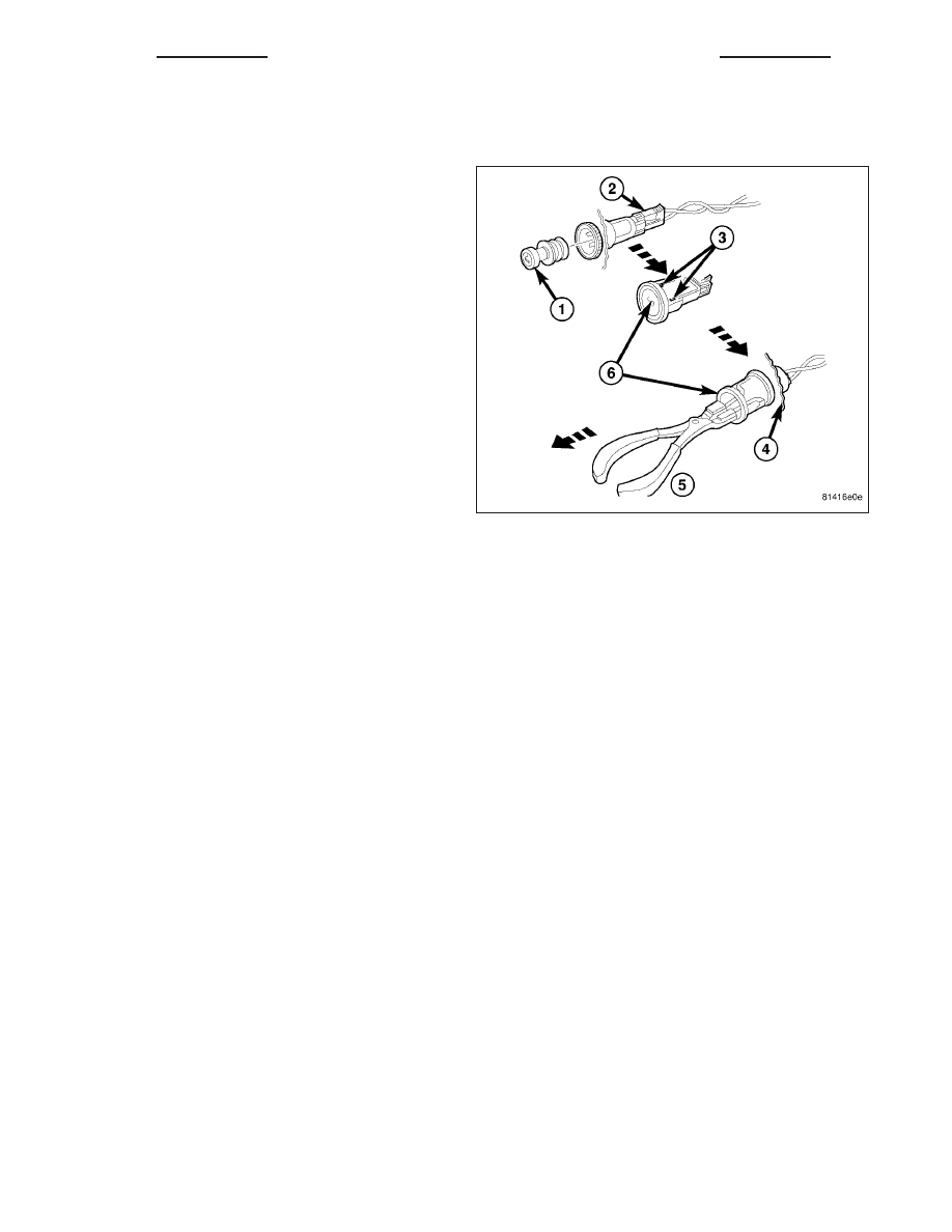
2. Pull the cigar lighter knob and element (1) out of
the cigar lighter receptacle base (6), or unsnap the
protective cap from the power outlet receptacle
base (6).
3. Look inside the cigar lighter or power outlet recep-
tacle base and note the position of the rectangular
retaining bosses (3) of the mount that secures the
receptacle base to the panel (4).
4. Insert a pair of external snap ring pliers (5) into the
cigar lighter or power outlet receptacle base and
engage the tips of the pliers with the retaining
bosses of the mount.
5. Squeeze the pliers to disengage the mount retain-
ing bosses from the receptacle base and, using a
gentle rocking motion, pull the pliers and the recep-
tacle base out of the mount.
6. Pull the receptacle base away from the instrument
panel far enough to access the instrument panel
wire harness connector (2).
7. Disconnect the instrument panel wire harness connector (2) from the cigar lighter or power outlet receptacle base
(6).
8. Remove the cigar lighter or power outlet mount from the instrument panel.
INSTALLATION
1. Connect the instrument panel wire harness connector to the cigar lighter or power outlet receptacle base con-
nector receptacle.
2. Install the cigar lighter or power outlet mount into the instrument panel.
3. Align the splines on the outside of the cigar lighter or power outlet receptacle base connector receptacle with the
grooves on the inside of the mount.
4. Press firmly on the cigar lighter or power outlet receptacle base until the retaining bosses of the mount are fully
engaged in their receptacles.
5. Install the cigar lighter knob and element into the cigar lighter receptacle base, or the protective cap into the
power outlet receptacle base.
6. Connect the battery negative cable.
8W - 97 - 8
8W-97 POWER DISTRIBUTION - SERVICE INFORMATION
ND
ENGINE
TABLE OF CONTENTS
page
page
ENGINE - 4.7L SERVICE INFORMATION . . . . . . 883
ENGINE ELECTRICAL DIAGNOSTICS
TABLE OF CONTENTS
page
page
ENGINE ELECTRICAL DIAGNOSTICS
PRE-DIAGNOSTIC TROUBLESHOOTING
PROCEDURE . . . . . . . . . . . . . . . . . . . . . . . . . 4
P0016–CRANKSHAFT / CAMSHAFT TIMING
MISALIGNMENT . . . . . . . . . . . . . . . . . . . . . . . 7
P0031-O2 SENSOR 1/1 HEATER CIRCUIT
LOW . . . . . . . . . . . . . . . . . . . . . . . . . . . . . . . 12
P0032-O2 SENSOR 1/1 HEATER CIRCUIT
HIGH . . . . . . . . . . . . . . . . . . . . . . . . . . . . . . . 16
P0037-O2 SENSOR 1/2 HEATER CIRCUIT
LOW . . . . . . . . . . . . . . . . . . . . . . . . . . . . . . . 21
P0038-O2 SENSOR 1/2 HEATER CIRCUIT
HIGH . . . . . . . . . . . . . . . . . . . . . . . . . . . . . . . 25
P0051-O2 SENSOR 2/1 HEATER CIRCUIT
LOW . . . . . . . . . . . . . . . . . . . . . . . . . . . . . . . 30
P0052-O2 SENSOR 2/1 HEATER CIRCUIT
HIGH . . . . . . . . . . . . . . . . . . . . . . . . . . . . . . . 34
P0057-O2 SENSOR 2/2 HEATER CIRCUIT
LOW . . . . . . . . . . . . . . . . . . . . . . . . . . . . . . . 39
P0058-O2 SENSOR 2/2 HEATER CIRCUIT
HIGH . . . . . . . . . . . . . . . . . . . . . . . . . . . . . . . 43
P0068-MANIFOLD PRESSURE/THROTTLE
POSITION CORRELATION . . . . . . . . . . . . . . . 48
SENSOR PERFORMANCE . . . . . . . . . . . . . . . 58
SENSOR CIRCUIT LOW . . . . . . . . . . . . . . . . 64
SENSOR CIRCUIT HIGH . . . . . . . . . . . . . . . . 67
P0107-MANIFOLD ABSOLUTE PRESSURE
SENSOR CIRCUIT LOW . . . . . . . . . . . . . . . . 71
P0108-MANIFOLD ABSOLUTE PRESSURE
SENSOR CIRCUIT HIGH . . . . . . . . . . . . . . . . 76
P0111-INTAKE AIR TEMPERATURE SENSOR
RATIONALITY . . . . . . . . . . . . . . . . . . . . . . . . 81
SENSOR CIRCUIT LOW . . . . . . . . . . . . . . . . 86
SENSOR CIRCUIT HIGH . . . . . . . . . . . . . . . . 89
P0116–ENGINE COOLANT TEMPERATURE
SENSOR CIRCUIT PERFORMANCE . . . . . . . 93
P0117-ENGINE COOLANT TEMPERATURE
SENSOR CIRCUIT LOW . . . . . . . . . . . . . . . . 98
P0118-ENGINE COOLANT TEMPERATURE
SENSOR CIRCUIT HIGH . . . . . . . . . . . . . . . 101
P0122-THROTTLE POSITION SENSOR 1
CIRCUIT LOW . . . . . . . . . . . . . . . . . . . . . . . 106
P0123-THROTTLE POSITION SENSOR 1
CIRCUIT HIGH . . . . . . . . . . . . . . . . . . . . . . . 111
P0125-INSUFFICIENT COOLANT TEMP FOR
CLOSED-LOOP FUEL CONTROL . . . . . . . . . 116
P0129-BAROMETRIC PRESSURE OUT-OF-
RANGE LOW . . . . . . . . . . . . . . . . . . . . . . . . 129
P0131-O2 SENSOR 1/1 CIRCUIT LOW
P0132-O2 SENSOR 1/1 CIRCUIT HIGH
P0133-O2 SENSOR 1/1 SLOW RESPONSE
PERFORMANCE . . . . . . . . . . . . . . . . . . . . . 148
P0137-O2 SENSOR 1/2 CIRCUIT LOW
P0138-O2 SENSOR 1/2 CIRCUIT HIGH
P0139-O2 SENSOR 1/2 SLOW RESPONSE
PERFORMANCE . . . . . . . . . . . . . . . . . . . . . 165
P0151-O2 SENSOR 2/1 CIRCUIT LOW
P0152-O2 SENSOR 2/1 CIRCUIT HIGH
P0153-O2 SENSOR 2/1 SLOW RESPONSE
PERFORMANCE . . . . . . . . . . . . . . . . . . . . . 182
ND
ENGINE
9 - 1
Нет комментариевНе стесняйтесь поделиться с нами вашим ценным мнением.
Текст