Mitsubishi Lancer Evolution IX. Manual — part 442
TROUBLESHOOTING
MULTIPORT FUEL INJECTION (MPI)
13A-243
Inspection Procedure 3: The Engine Warning Lamp does not Illuminate Right after the Ignition Switch
is Turned to the "ON" Position
AK501825
6
5
4
3
2
1
12
11
10
15 16
14
13
17
20 21
19
18
9
8
7
1 2 3
4 5 6
2
3 4
5 6
7 8
9
11 12 13 14 15 16 17 18 19 20
30
21 22 23
24 25
26 27 28 29
3132 33
34 35
1
10
R
IG2
ST
LOCK
ACC
IG1
2
7.5A
6
C-211
25
C-214
Ignition switch
C-208
2
B-W
Y-R
O
Y-R
W-L
W-L
19
17
J/B
C-01
Engine-ECU
9
22
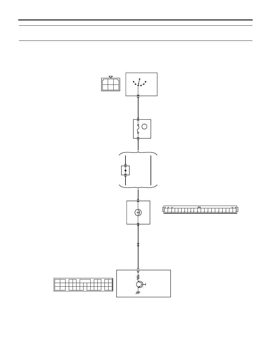
Engine warning lamp (check engine lamp) circuit
Engine warning lamp (check engine lamp)
9
17
Wire colour code
B: Black LG: Light green G: Green L: Blue W: White Y: Yellow SB: Sky blue BR: Brown O: Orange GR: Gray
R: Red P: Pink V: Violet PU: Purple
AB
C-121
(MU803784)
NOTE
*1: L.H. drive vehicles
*2: R.H. drive vehicles
*1
*2
J/C (4)
C-23
Chec
k
engine
C-124

TROUBLESHOOTING
MULTIPORT FUEL INJECTION (MPI)
13A-244
OPERATION
• Battery voltage is applied to engine warning lamp
of combination meter connector (terminal No. 9)
from ignition switch.
• Engine-ECU (terminal No. 22) makes power tran-
sistor in unit be in "ON" position, and that makes
currents go on engine warning lamp of combina-
tion meter connector (terminal No. 17).
COMMENTS ON TROUBLE SYMPTOM
• Engine-ECU turns on engine warning lamp for 5
seconds to check for burnt-out bulb immediately
after ignition switch is turned to ON.
• If engine warning lamp is not lit just after turning
ignition switch to "ON" position, failure is possibly
caused by burn-out bulb, open/short circuit or
other faults.
PROBABLE CAUSES
• Engine warming lamp bulb burnt out
• Failed ignition switch
• Open/short circuit in engine warning lamp circuit
or loose connector contact
• Failed engine-ECU
DIAGNOSIS PROCEDURE
STEP 1. Check engine start-up.
Q: Is engine started?
YES :
Go to Step 2 .
NO :
Check engine-ECU power supply, engine
control relay and ignition switch IG1 system
(Refer to Inspection Procedure 23
).
STEP 2. Check engine warning lamp for
burnt-out bulb.
Q: Is the check result normal?
YES :
Go to Step 3 .
NO :
Replace the engine warning lamp.
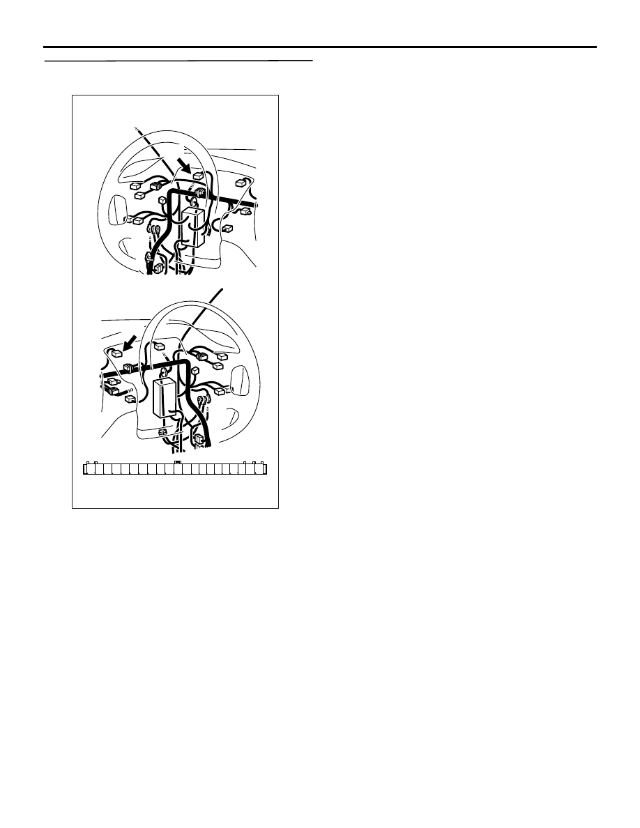
STEP 3. Connector check: C-01 combination
meter connector
Q: Is the check result normal?
YES :
Go to Step 4 .
NO :
Repair or replace the connector.
AK301236
6 5 4 3 2 1
12 11 10
15
16
14 13
21
18 17
19
20
9 8 7
Harness side connector
Connector: C-01
C-01
<L. H. drive vehicles>
<R. H. drive vehicles>
C-01
AC
TROUBLESHOOTING
MULTIPORT FUEL INJECTION (MPI)
13A-245
STEP 4. Perform voltage measurement at C-01
combination meter connector.
• Disconnect connector, and measure at the har-
ness side.
• Ignition switch: "ON"
• Voltage between terminal No. 9 and earth.
OK: System voltage
Q: Is the check result normal?
YES :
Go to Step 6 .
NO :
Go to Step 5 .
AK301236
6 5 4 3 2 1
12 11 10
15
16
14 13
21
18 17
19
20
9 8 7
Harness side connector
Connector: C-01
C-01
<L. H. drive vehicles>
<R. H. drive vehicles>
C-01
AC
TROUBLESHOOTING
MULTIPORT FUEL INJECTION (MPI)
13A-246
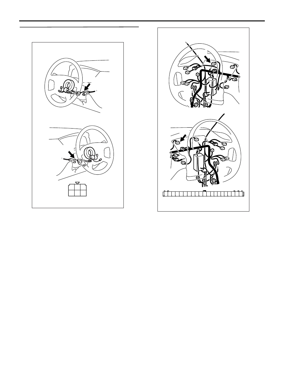
STEP 5. Connector check: C-208 ignition switch
connector
Q: Is the check result normal?
YES :
Check intermediate connectors C-23 <L.H.
drive vehicles> or C-214 and C-211, and
repair if necessary. If intermediate
connectors are normal, check and repair
harness between C-01 (terminal No. 9)
combination meter connector and C-208
(terminal No. 2) ignition switch connector.
• Check power supply line for
open/short circuit.
NO :
Repair or replace the connector.
AK305251
1
2
3
4
5
6
Harness side connector
Connector: C-208
C-208
<L. H. drive vehicles>
<R. H. drive vehicles>
C-208
AB
AK301236
6 5 4 3 2 1
12 11 10
15
16
14 13
21
18 17
19
20
9 8 7
Harness side connector
Connector: C-01
C-01
<L. H. drive vehicles>
<R. H. drive vehicles>
C-01
AC
Нет комментариевНе стесняйтесь поделиться с нами вашим ценным мнением.
Текст