Mitsubishi Lancer Evolution IX. Manual — part 171

INPUT SIGNAL PROCEDURES
SMART WIRING SYSTEM (SWS) NOT USING SWS MONITOR
54B-247
Step 4. Connector check: C-226 ETACS-ECU
connector
Q: Is the check result normal?
YES :
Go to Step 5.
NO :
Repair the defective connector.
Step 5. Check the wiring harness between D-01
door switch (front: RH) connector terminal No.3
and C-226 ETACS-ECU connector terminal No.10.
NOTE:
Prior to the wiring harness inspection, check joint
connector C-217, and repair if necessary.
• Check the input line for open circuit.
Q: Is the check result normal?
YES :
Go to Step 6.
NO :
Repair the wiring harness.
Step 6. Retest the system.
Check that the door switch (front: RH) signal is
received normally.
Q: Is the check result normal?
YES :
The trouble can be an intermittent
malfunction (Refer to GROUP 00
− How to
Cope with Intermittent Malfunction
NO :
Replace the ETACS-ECU.
AC310461
Junction block (rear view)
Connector: C-226
AB
<RHD>
Junction block side
AC310461
Junction block (rear view)
Connector: C-226
AB
<RHD>
Junction block side
AC310471
Harness side
AB
Connector: D-01
<RHD>
AC310458
Harness side
Junction block (front view)
Connector: C-217
AC
<RHD>

INPUT SIGNAL PROCEDURES
SMART WIRING SYSTEM (SWS) NOT USING SWS MONITOR
54B-248
INSPECTION PROCEDURE L-4: The column switch (lighting and turn-signal lamp switch) signal is not
received.
CAUTION
Whenever the ECU is replaced, ensure that the
input signal circuit is normal.
COMMENTS ON TROUBLE SYMPTOM
Input signal from the column switch (lighting and
turn-signal lamp switch) is used to operate the func-
tions below. If the signal is abnormal, these functions
will not work normally.
• Lamp reminder function
• Headlamp and tail lamp
• Fog lamp
• Turn signal lamp
POSSIBLE CAUSES
• Malfunction of the column switch
• Damaged harness wires and connectors
DIAGNOSTIC PROCEDURE
Step 1. Check the column switch connector.
Check that the wiper and washer switch connector,
the lighting switch connector and the switch body
connector are in good condition.
Q: Is the check result normal?
YES :
Go to Step 2.
NO :
Repair the defective connector.
Step 2. Check the column switch (lighting switch
and switch body).
Refer to GROUP 54A
− Column switch
.
Q: Is the check result normal?
YES :
Go to Step 3.
NO :
Replace the column switch.
Step 3. M.U.T.-II/III diagnosis code.
Check that the ETACS-ECU sets a diagnosis code.
Q: Is the diagnosis code set?
YES :
Refer to diagnosis code chart
.
NO :
Go to Step 4.
Step 4. Retest the system.
Replace the column switch, and check if the column
switch (lighting, turn-signal lamp) sends signal.
(1) Replace the column switch.
(2) Check if the column switch (lighting and
turn-signal switch) sends signal.
Q: Is the check result normal?
YES :
The procedure is complete.
NO :
Replace the ETACS-ECU.
COLUMN-ECU
DIMMER·
PASSING SWITCH
TURN-SIGNAL
LAMP SWITCH
LIGHTING
SWITCH
COLUMN SWITCH
Lighting Switch Input Circuit
INPUT SIGNAL PROCEDURES
SMART WIRING SYSTEM (SWS) NOT USING SWS MONITOR
54B-249
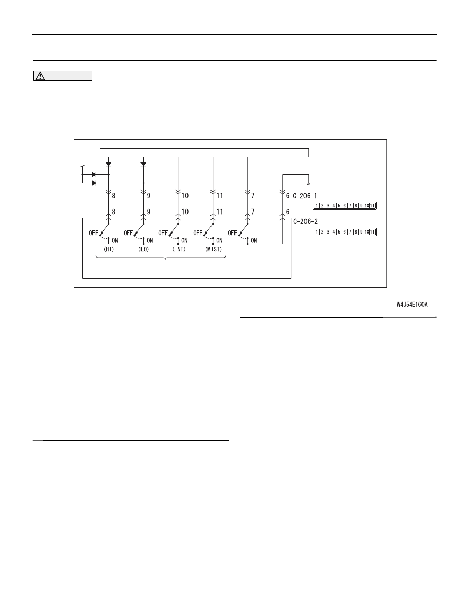
INSPECTION PROCEDURE L-5: The column switch (windshield wiper/washer) signal is not received.
CAUTION
Whenever the ECU is replaced, ensure that the
input signal circuit is normal.
COMMENTS ON TROUBLE SYMPTOM
Input signal from the column switch (wiper switch) is
used to operate the functions below. If the signal is
abnormal, these functions will not work normally.
• Windshield wiper and washer
POSSIBLE CAUSES
• Malfunction of the column switch
• Damaged harness wires and connectors
DIAGNOSTIC PROCEDURE
Step 1. M.U.T.-II/III diagnosis code.
Check that the ETACS-ECU sets a diagnosis code.
Q: Is the diagnosis code set?
YES :
Refer to diagnosis code chart
NO :
Go to Step 2.
Step 2. Retest the system.
Replace the column switch, and check if the column
switch (windshield wiper washer) sends signal.
(1) Replace the column switch.
(2) Check if the column switch (windshield
wiper/washer) sends signal.
Q: Is the check result normal?
YES :
The procedure is complete.
NO :
Replace the ETACS-ECU.
WINDSHIELD
WASHER
SWITCH
WINDSHIELD
WIPER SWITCH
UPPER
SIDE
UPPER
SIDE
COLUMN SWITCH
COLUMN-ECU
Windshield Wiper and Washer Switch Input Circuit
INPUT SIGNAL PROCEDURES
SMART WIRING SYSTEM (SWS) NOT USING SWS MONITOR
54B-250
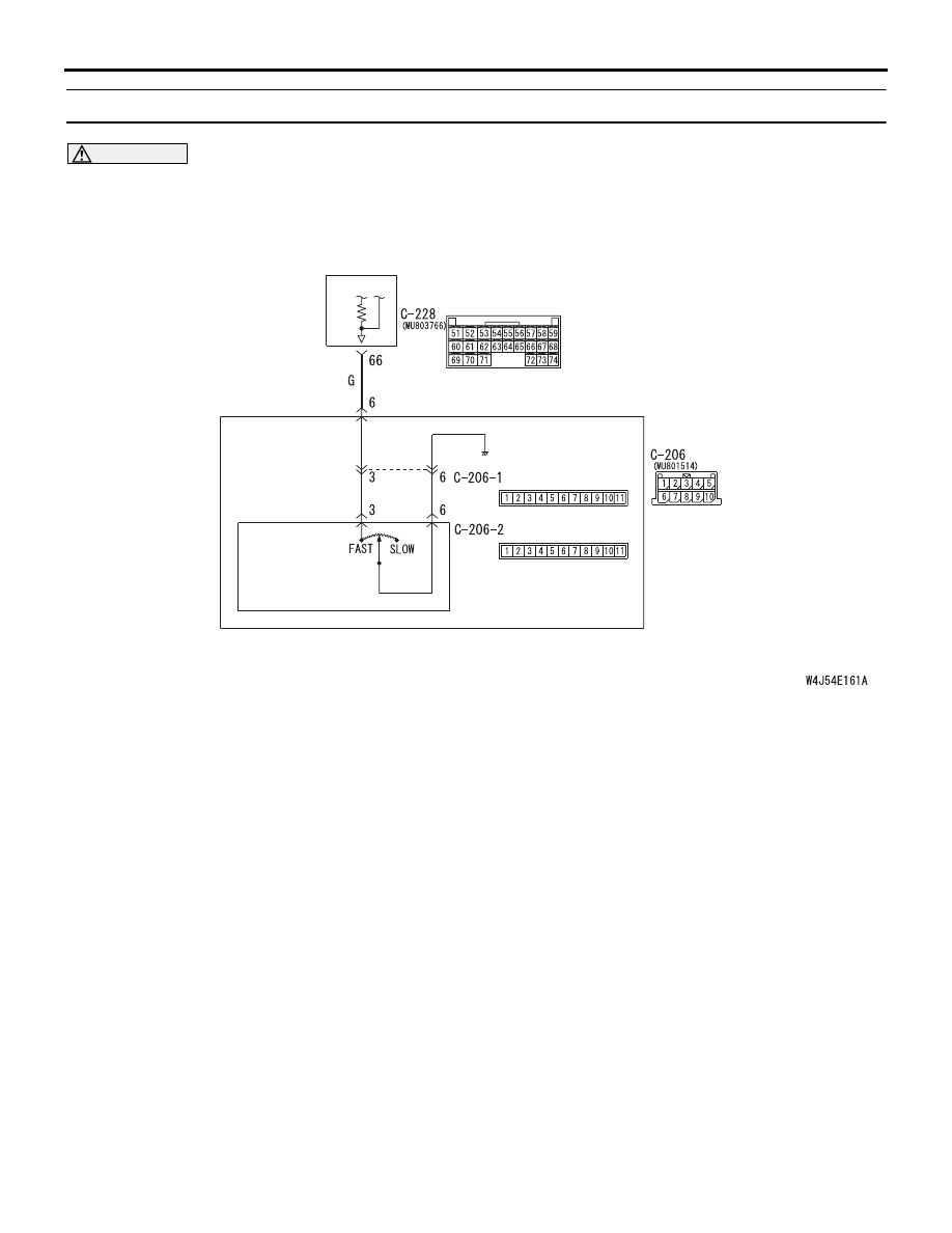
INSPECTION PROCEDURE L-6: The windshield intermittent wiper volume signal is not received.
CAUTION
Whenever the ECU is replaced, ensure that the
input signal circuit is normal.
COMMENTS ON TROUBLE SYMPTOM
The intermittent wiper interval is calculated in
accordance with the input signal from the windshield
intermittent wiper volume. If this signal is abnormal,
the wiper interval can not be adjusted.
POSSIBLE CAUSES
• Malfunction of the column switch
• Malfunction of the ETACS-ECU
• Damaged harness wires and connectors
COLUMN
SWITCH
WINDSHIELD
INTERMITTENT
WIPER INTERVAL
ADJUSTING KNOB
UPPER
SIDE
UPPER
SIDE
ETACS-
ECU
Wire colour code
B : Black LG : Light green G : Green L : Blue W : White Y : Yellow SB : Sky blue
BR : Brown O : Orange GR : Gray R : Red P : Pink V : Violet
Windshield Intermittent Wiper Interval Adjusting Knob Input Circuit
Нет комментариевНе стесняйтесь поделиться с нами вашим ценным мнением.
Текст