Mitsubishi Lancer Evolution IX. Manual — part 640
TROUBLESHOOTING
SUPPLEMENTAL RESTRAINT SYSTEM (SRS)
52B-73
DIAGNOSIS PROCEDURE
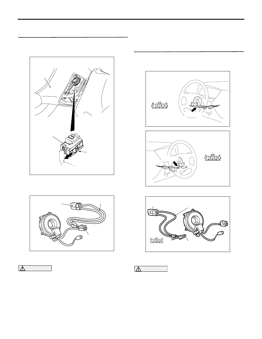
STEP 1. Check the diagnosis code by connecting
a dummy resistor. (M.U.T.-II/III diagnosis code)
(1) Disconnect the negative battery terminal.
(2) By sliding the A section (in the figure) of air bag
module connector C-201 in arrow direction,
disconnect the connector.
(3) Connect special tool dummy resistor (MB991865)
to special tool resistor harness (MB991866).
CAUTION
Do not insert a test probe into the terminal from
its front side directly as the connector contact
pressure may be weakened.
(4) Insert special tool (MB991866) into clock spring
side air bag module connector C-201 by
backprobing.
(5) Connect the negative battery terminal.
(6) Erase the diagnosis code memory, and check the
diagnosis code.
Q: Is diagnosis code 62 out put?
YES :
Go to Step 2.
NO :
Replace the driver’s air bag module (Refer
to
STEP 2. Check the diagnosis code by connecting
a dummy resistor. (M.U.T.-II/III diagnosis code)
(1) Disconnect the negative battery terminal.
(2) Disconnect the clock spring connector C-205.
(3) Connect special tool dummy resistor (MB991865)
to special tool resistor harness (MB991866).
CAUTION
Do not insert a test probe into the terminal from
its front side directly as the connector contact
pressure may be weakened.
(4) Insert special tool (MB991866) into clock spring
harness side connector C-205 (terminal No.3 and
4) by backprobing.
(5) Connect the negative battery terminal.
(6) Erase the diagnosis code memory, and check the
diagnosis code.
AC105823
AC304700
AC305145AE
A
Steering
wheel
C-201 Air bag
module connector
AC300945AE
MB991865
(Dummy resistor : 3 )
MB991866
(Resistor harness)
C-201 Air bag
module
connector
AC310479
AG
Connector: C-205 <LHD>
C-205 (Y)
Harness side
connector
(rear view)
AC310481AG
Connector: C-205 <RHD>
C-205 (Y)
Harness side
connector
(rear view)
AC300949AC
MB991865 (Dummy
resistor : 3 )
MB991866
(Resistor harness)
C-205 Clock spring
connector
(Rear view)

TROUBLESHOOTING
SUPPLEMENTAL RESTRAINT SYSTEM (SRS)
52B-74
Q: Is diagnosis code 62 set?
YES :
Go to Step 3.
NO :
Replace the clock spring (Refer to
).
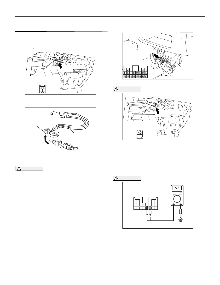
STEP 3. Resistance measurement at the
SRS-ECU connector C-12
(1) Disconnect SRS-ECU connector C-12.
DANGER
To prevents the air bag from deploying unin-
tentionally, disconnect the clock spring con-
nector C-205 to short the squib circuit.
(2) Disconnect the clock spring connector C-205.
CAUTION
Do not insert a test probe into the terminal from
its front side directly as the connector contact
pressure may be weakened.
(3) Check for continuity between C-12 harness side
connector terminals 11, 12 and body earth.
OK: Open circuit
Q: Is the check result normal?
YES :
Go to Step 4.
NO :
Repair the harness wires between
SRS-ECU connector C-12 (terminal No.11
and 12) and clock spring connector C-205
(terminal No.3 and 4).
STEP 4. Check whether the diagnosis code is
reset.
Q: Is diagnosis code 62 set?
YES :
Replace the SRS-ECU (Refer to
).
NO :
An intermittent malfunction is suspected
(Refer to GROUP 00
− How to Use
Troubleshooting/Inspection Service Points
).
AC101950AJ
SRS-ECU
Harness side
connector
(rear view)
C-12 (Y)
Connector: C-12
AC310479
AG
Connector: C-205 <LHD>
C-205 (Y)
Harness side
connector
(rear view)
AC310481AG
Connector: C-205 <RHD>
C-205 (Y)
Harness side
connector
(rear view)
AC006256
13 14 15 16 17 18 19 20
5 6 7 8 9 10 11 12
1 2
3 4
AS
C-12 Harness side
connector (rear view)

TROUBLESHOOTING
SUPPLEMENTAL RESTRAINT SYSTEM (SRS)
52B-75
Code No.64: Passenger's (front) air bag module (squib) system (short-circuited to the power supply)
OPERATION
• The SRS-ECU judges how severe a collision is
by detecting signals from the front impact sensors
and the front air bag analogue G-sensor. If the
impact is over a predetermined level, the
SRS-ECU outputs an ignition signal. At this time,
if the front air bag safing G-sensor is on, the SRS
air bag will inflate.
• The ignition signal is input to the air bag module
to inflate the air bag.
DIAGNOSIS CODE SET CONDITIONS
This diagnosis code is set if the passenger's (front)
air bag squib wire(s) are short-circuited to the power
supply.
PROBABLE CAUSES
• Damaged harness wires and connectors
• Short to the power supply in the passenger's
(front) air bag module (squib) harness
• Malfunction of the SRS-ECU
CONNECTOR
LOCK
SWITCH
CONNECTOR
LOCK
SWITCH
AIR BAG DRIVE
CIRCUIT
MICROCOMPUTER
SRS-ECU
AIR BAG MODULE
(SQUIB)
(PASSENGER'S SIDE)
Wire colour code
B : Black LG : Light green
G : Green L : Blue
W : White Y : Yellow
SB : Sky blue BR : Brown
O : Orange GR : Gray
R : Red P : Pink V : Violet
Passenger's (Front) Air Bag Module (Squib) Circuit
NOTE
: CONNECTOR
COUPLED: ON
CONNECTOR
UNCOUPLED: OFF
: LH drive vehicles
: RH drive vehicles
TROUBLESHOOTING
SUPPLEMENTAL RESTRAINT SYSTEM (SRS)
52B-76
DIAGNOSIS PROCEDURE
STEP1. Check the diagnosis code by connecting
a dummy resistor. (M.U.T.-II/III diagnosis code)
(1) Disconnect the negative battery terminal.
(2) Disconnect passenger’s (front) air bag module
connector C-106.
(3) Connect special tool dummy resistor (MB991865)
to special tool resistor harness (MB991866).
CAUTION
Do not insert a test probe into the terminal from
its front side directly as the connector contact
pressure may be weakened.
(4) Disconnect the passenger's (front) air bag
module connector C-106, and insert special tool
(MB991866) into the harness side connector by
backprobing.
(5) Connect the negative battery terminal.
(6) Erase the diagnosis code memory, and check the
diagnosis code.
Q: Is diagnosis code 64 set?
YES :
Go to Step 2.
NO :
Replace the passenger's (front) air bag
module (Refer to
STEP 2. Voltage measurement at the SRS-ECU
connector C-12
(1) Disconnect SRS-ECU connector C-12.
CAUTION
To prevents the air bag from deploying uninten-
tionally, disconnect the passenger’s (front) air
bag module connector C-106 to short the squib
circuit.
(2) Disconnect the passenger's (front) air bag
module connector C-106.
(3) Turn the ignition switch to the "ON" position.
CAUTION
Do not insert a test probe into the terminal from
its front side directly as the connector contact
pressure may be weakened.
(4) Voltage measurement between C-12 harness
side connector terminals 9, 10 and body earth.
OK: 0 V
AC100985
Connector: C-106
Glove box striker
2
1
Harness side
connector (rear view)
C-106 (R)
AQ
AC300956AL
MB991865
(Dummy resistor: 3 )
MB991866
(Resistor harness)
C-106 Passenger's (front)
air bag module connector
C-106 Harness side
connector
AC101950AJ
SRS-ECU
Harness side
connector
(rear view)
C-12 (Y)
Connector: C-12
AC100985
Connector: C-106
Glove box striker
2
1
Harness side
connector (rear view)
C-106 (R)
AQ
13 14 15 16 17 18 19 20
5 6 7 8 9 10 11 12
1 2
3 4
AC006257AR
C-12 Harness side
connector (rear view)
Нет комментариевНе стесняйтесь поделиться с нами вашим ценным мнением.
Текст