Mitsubishi Lancer Evolution IX. Manual — part 358

EMISSION CONTROL <MPI>
ENGINE AND EMISSION CONTROL
17-11
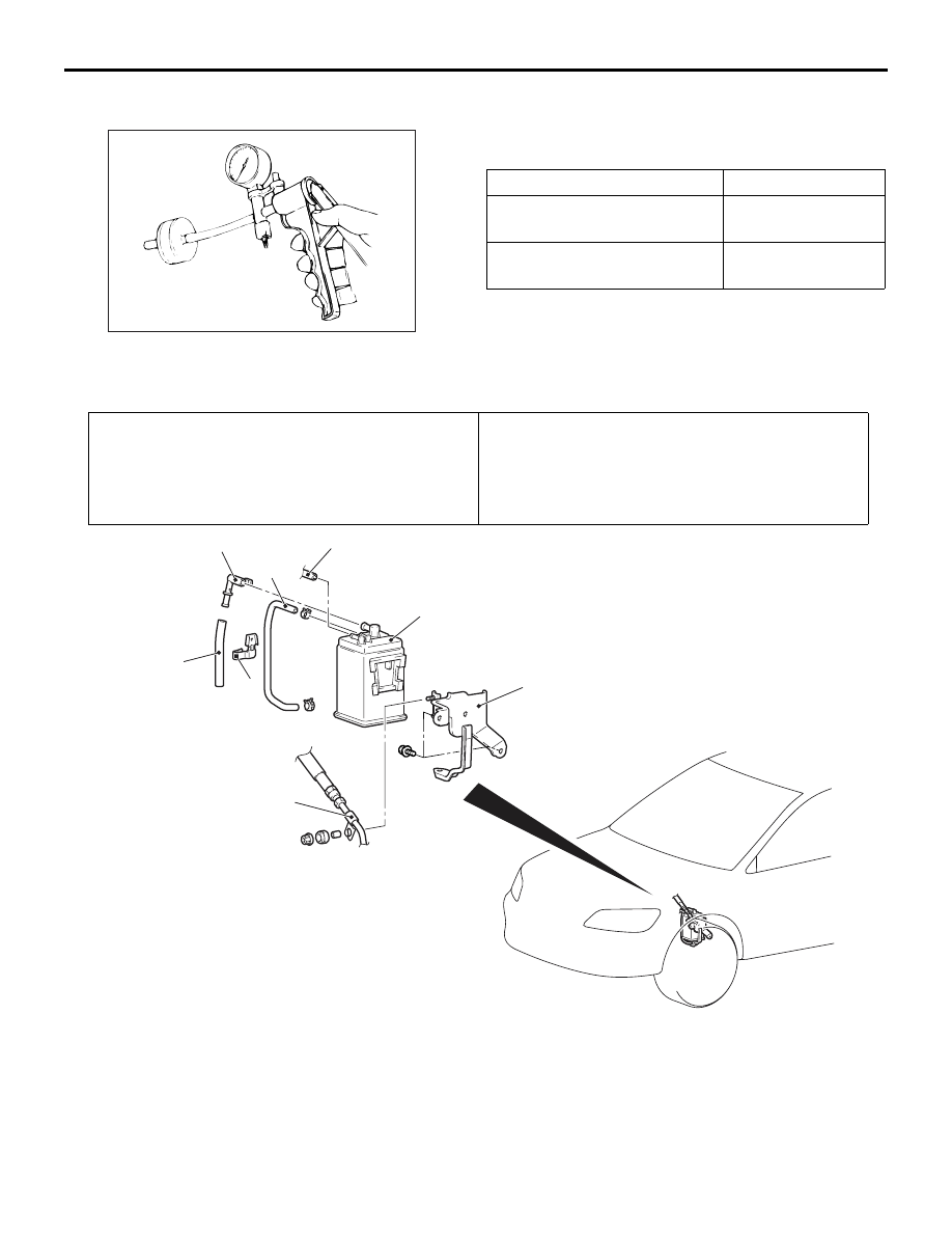
PURGE PORT VACUUM CHECK
M1173001500252
AK304231AB
Red stripe
Throttle body
1. Disconnect the vacuum hose (red stripe) from the
throttle body and connect a hand vacuum pump to
the nipple.
2. Plug the vacuum hose (red stripe).
AK100011
AC
Vac-
uum
Engine speed (r/min)
3. Start the engine.
4. Check that a fairly constant negative pressure is
generated regardless of the engine speed.
5. If no negative pressure is generated, the port is
probably blocked and should be cleaned.
PURGE CONTROL SOLENOID VALVE
CHECK
M1173001700405
NOTE: When disconnecting the vacuum hose,
always make a mark so that it can be reconnected at
original position.
AK100012 AC
Battery
A
1. Disconnect the vacuum hose from the solenoid
valve.
2. Disconnect the harness connector.
3. Connect a hand vacuum pump to nipple (A) of the
solenoid valve (refer to the illustration at left).
4. Check airtightness by applying negative pressure
with voltage applied directly from the battery to the
purge control solenoid valve and without applying
voltage.
Battery voltage
Normal condition
Applied
Negative pressure
leaks
Not applied
Negative pressure
maintained
AK100013
5. Measure the resistance between the terminals of
the solenoid valve.
Standard value: 30
− 34 Ω (at 20°C)
EMISSION CONTROL <MPI>
ENGINE AND EMISSION CONTROL
17-12
CHECK VALVE CHECK
M1173006200085
AK200373
Connect a hand vacuum pump to the check valve,
apply negative pressure and check the airtightness.
Connect nipple colour
Normal condition
Black
Negative pressure
leaks
Brown
Negative pressure
is maintained
FUEL VAPOUR CANISTER REMOVAL AND INSTALLATION
M1173004200186
Pre-removal Operation
• Air Pipe C, Air Hose D Removal (Refer to GROUP 15,
Intercooler
• Battery and Battery Tray Removal
• Air Cleaner Assembly Removal (Refer to GROUP 15, Air
Cleaner
).
Post-installation Operation
• Air Cleaner Assembly Installation (Refer to GROUP 15,
Air Cleaner
).
• Battery and Battery Tray Installation
• Air Pipe C, Air Hose D Installation (Refer to GROUP 15,
Intercooler
AC310639
AB
1
2
3
4
5
6
7
8
Removal steps
1.
Emission vacuum hose connection
2.
Fuel vapour control line hose
3.
Fuel vapour control check valve
4.
Fuel vapour control line hose
5.
Fuel vapour control line clamp
6.
Fuel vapour canister
7.
Fuel high-pressure hose clamp
8.
Fuel vapour canister bracket
Removal steps (Continued)
EMISSION CONTROL <MPI>
ENGINE AND EMISSION CONTROL
17-13
EXHAUST GAS RECIRCULATION (EGR) SYSTEM
GENERAL INFORMATION (EGR SYSTEM)
M1173005200684
The exhaust gas recirculation (EGR) system lowers
the nitrogen oxide (NOx) emission level.
When the air/fuel mixture combustion temperature is
high, a large quantity of NOx is generated in the
combustion chamber.
Therefore, this system recirculates part of emission
gas from the exhaust port of the cylinder head to the
combustion chamber through the inlet manifold to
decrease the air/fuel mixture combustion tempera-
ture, resulting in reduction of NOx.
The EGR flow rate is controlled by the EGR valve so
as not to decrease the driveability.
OPERATION
The EGR valve is being closed and does not recircu-
late exhaust gases under one of the following condi-
tions.
Otherwise, the EGR valve is opened and recirculates
exhaust gases.
• The engine coolant temperature is low.
• The engine is at idle.
• The throttle valve is widely opened.
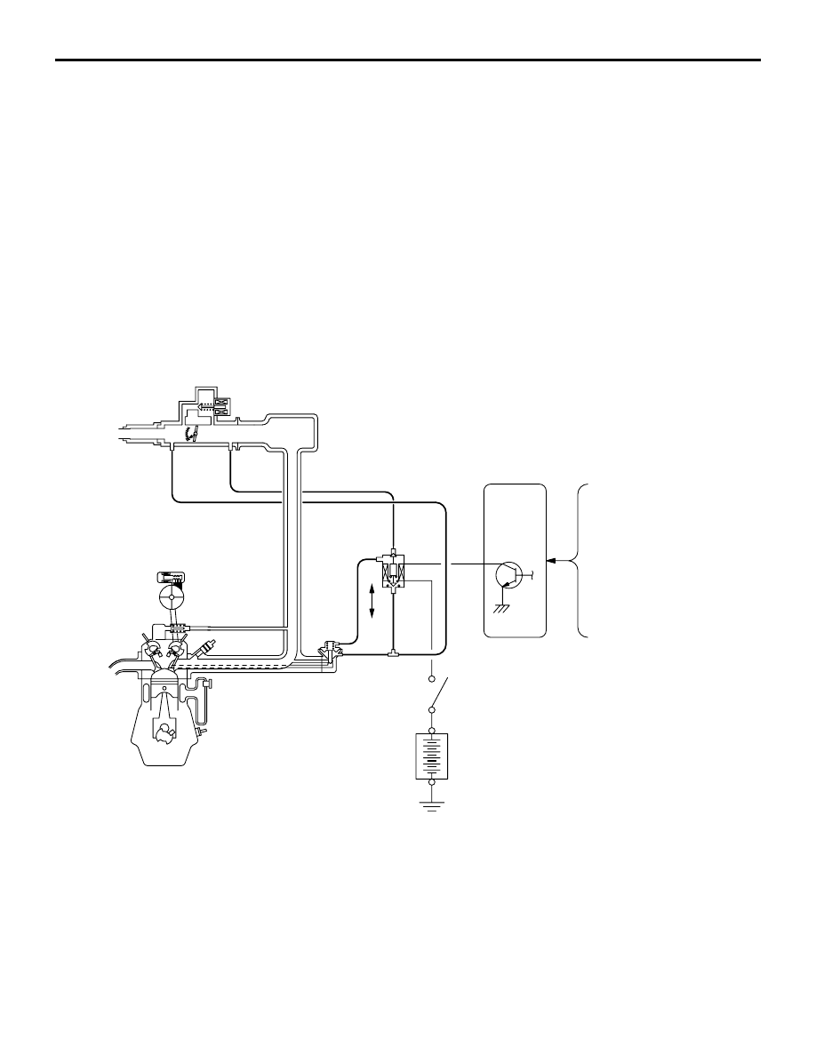
SYSTEM DIAGRAM
AK501846 AB
Air flow sensor
Engine coolant
temperature sensor
Crank angle sensor
Barometric
pressure sensor
EGR control
Solenoid valve
Engine
control
relay
Battery
OFF
EGR valve
ON
Engine-ECU

EMISSION CONTROL <MPI>
ENGINE AND EMISSION CONTROL
17-14
COMPONENT LOCATION (EGR SYSTEM)
M1173007600309
AK304234AB
EGR control
solenoid valve
AK304235AB
EGR valve
EGR SYSTEM CHECK
M1173002600393
AK304236AB
EGR control
solenoid valve
Green stripe
Three-way terminal
1. Disconnect the vacuum hose (Green stripe) from
the EGR valve, and then connect a hand vacuum
pump via the three-way terminal.
2. When the engine is hot or cold, check the
condition of vacuum by racing the engine.
When engine is cold
(Engine coolant temperature: 20
°C or less)
Throttle valve
Normal vacuum
condition
Open quickly
No vacuum will
generate (the same
as barometric
pressure.)
When engine is hot
(Engine coolant temperature: 80
°C or higher)
Throttle valve
Normal vacuum
condition
Open quickly
It will momentarily
rise over 13 kPa
3. Disconnect the three-way terminal.
AK304237AB
EGR control
solenoid valve
Green stripe
4. Connect the hand vacuum pump to the EGR
valve nipple (Green stripe).
5. Check whether the engine stalls or the idling is
unstable when a vacuum of 27 kPa or higher is
applied during idling.
Нет комментариевНе стесняйтесь поделиться с нами вашим ценным мнением.
Текст