Mitsubishi Lancer Evolution IX. Manual — part 508
TROUBLESHOOTING
ANTI-SKID BRAKING SYSTEM (ABS)
35B-63
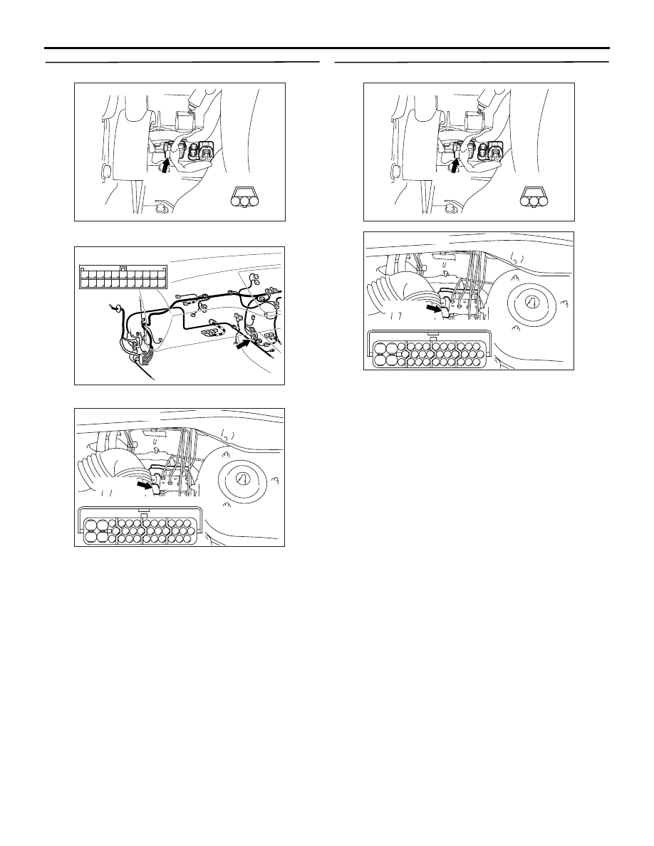
STEP 9. Check the following connectors.
•
Longitudinal G-sensor connector D-38
•
Intermediate connector C-122
•
ABS-ECU connector B-118
Check the connectors for loose, corroded or dam-
aged terminals, or terminals pushed back in the con-
nector.
Q: Are the connectors and terminals in good
condition?
YES :
Go to Step 10.
NO :
Repair it and then go to Step 11.
STEP 10. Check the following harness wire.
The wire between longitudinal G-sensor connector
D-38 (terminal 2) and ABS-ECU connector B-118
(terminal 25)
Q: Is the harness wire damaged?
YES :
Repair or replace it and then go to Step 11.
NO :
Replace the brake modulator hydraulic unit
(integrated with ABS-ECU) (Refer to
). Then go to Step 11.
AC311167AB
Connector: D-38
D-38 (B)
Harness side
3
1
2
AC311160AC
Connector: C-122
C-122 (L)
2
1
3
13
12
14
21
10
5
4
6
16
15
17
7 8 9
19
18
20
11
22
AC311127AB
B-118 (B)
Connector: B-118
28
32
34
12
11
33
30
21
9
10
22
31
7
8
29
20 19
24
2
26
4
5
6
27
18 17
3
25
16 15
1
23
13
14
Harness side
AC311167AB
Connector: D-38
D-38 (B)
Harness side
3
1
2
AC311127AB
B-118 (B)
Connector: B-118
28
32
34
12
11
33
30
21
9
10
22
31
7
8
29
20 19
24
2
26
4
5
6
27
18 17
3
25
16 15
1
23
13
14
Harness side
TROUBLESHOOTING
ANTI-SKID BRAKING SYSTEM (ABS)
35B-64
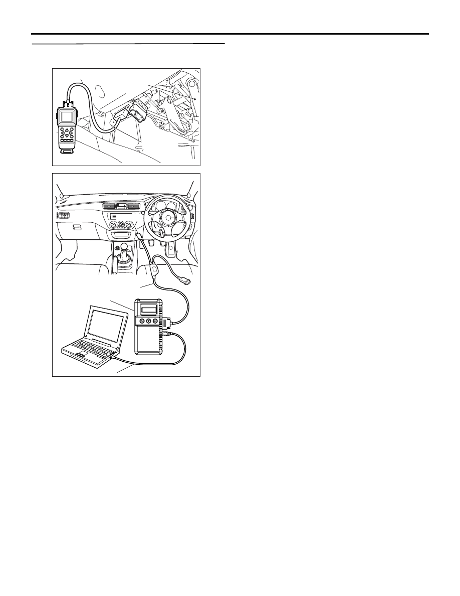
STEP 11. Check whether the diagnosis code is
reset.
Check again if the diagnosis code is set.
(1) Turn the ignition switch to the "ON" position.
(2) Erase the diagnosis code.
(3) Turn the ignition switch to the "LOCK" (OFF)
position.
(4) Turn the ignition switch to the "ON" position.
(5) Check if the diagnosis code is set.
(6) Turn the ignition switch to the "LOCK" (OFF)
position.
Q: Does diagnosis code No.32 reset?
YES :
Start over at Step 1.
NO :
The procedure is complete.
AC311157
Steering shaft
AB
MB991502
<Using the M.U.T.-II>
AC311153
AB
MB991911
16-PIN
MB991827
MB991824
<Using the M.U.T.-III>
TROUBLESHOOTING
ANTI-SKID BRAKING SYSTEM (ABS)
35B-65
Code No.41: Front Right Solenoid Valve inside Hydraulic Unit
Code No.42: Front Left Solenoid Valve inside Hydraulic Unit
Code No.43: Rear Right Solenoid Valve inside Hydraulic Unit
Code No.44: Rear Left Solenoid Valve inside Hydraulic Unit
Code No.52: Valve Relay Problem (Stays off)
Code No.53: Motor Relay Problem (Stays off)
Code No.55: Motor System (Seized Pump Motor)
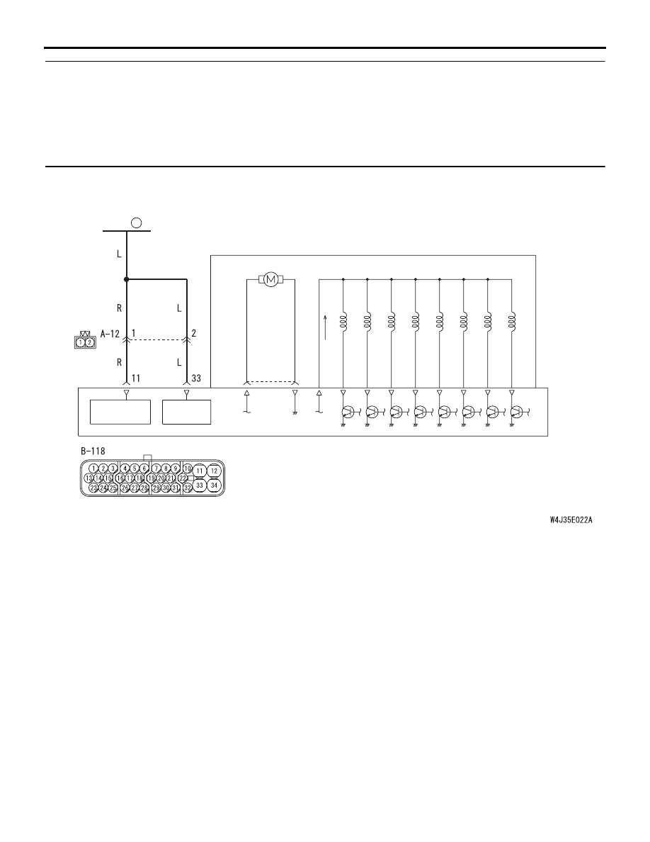
OPERATION
Power is continuously supplied to the ABS-ECU
through fusible link number 3 to operate the solenoid
valve and motor.
DIAGNOSIS CODE SET CONDITIONS
These codes are displayed if the power supply circuit
of solenoid valve or motor is open or shorted.
PROBABLE CAUSES
The most likely causes for these diagnosis codes to
set are:
• Damaged wiring harness or connector
• Malfunction of the brake modulator hydraulic unit
(integrated with ABS-ECU)
SOLENOID
VALVE POWER
SUPPLY
MOTOR
POWER
SUPPLY
SOLENOID VALVE
MOTOR
HYDRAULIC UNIT
FUSIBLE
LINK
3
ABS-ECU
Wire colour code
B : Black LG : Light green G : Green L : Blue
W : White Y : Yellow SB : Sky blue BR : Brown
O : Orange GR : Gray R : Red P : Pink V : Violet
Solenoid Valve and Motor Power Supply Circuit
TROUBLESHOOTING
ANTI-SKID BRAKING SYSTEM (ABS)
35B-66
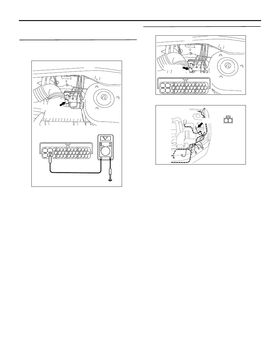
DIAGNOSIS
STEP 1. Check the solenoid valve or motor power
supply circuit. Voltage measurement at ABS-ECU
connector B-118.
(1) Disconnect ABS-ECU connector B-118 and
measure at the harness side.
(2) Measure the voltage between terminal 11 and
earth, and 33 and earth.
OK: System voltage
Q: Is the check result normal?
YES :
Replace the brake modulator hydraulic unit
(integrated with ABS-ECU) (Refer to
). Then go to Step 4.
NO :
Go to Step 2.
STEP 2. Check the following connectors.
•
ABS-ECU connector B-118
•
Intermediate connector A-12
Check the connectors, for loose, corroded or dam-
aged terminals, or terminals pushed back in the con-
nector.
Q: Are the connectors and terminals in good
condition?
YES :
Go to Step 3.
NO :
Repair it and then go to Step 4.
AC311168
28
32
34
12
11
33
30
21
9
10
22
31
7
8
29
20 19
24
2
26
4
5
6
27
18 17
3
25
16 15
1
23
13
14
Connector B-118
(Harness side)
AB
B-118 (B)
Connector: B-118
AC311127AB
B-118 (B)
Connector: B-118
28
32
34
12
11
33
30
21
9
10
22
31
7
8
29
20 19
24
2
26
4
5
6
27
18 17
3
25
16 15
1
23
13
14
Harness side
AC311169AB
Connector: A-12
A-12 (B)
1 2
Нет комментариевНе стесняйтесь поделиться с нами вашим ценным мнением.
Текст