Mitsubishi Lancer Evolution IX. Manual — part 530
36-1
GROUP 36
CONTENTS
GENERAL INFORMATION . . . . . . . .
SERVICE SPECIFICATIONS. . . . . . .
LUBRICANTS . . . . . . . . . . . . . . . . . .
ON-VEHICLE SERVICE. . . . . . . . . . .
PARKING BRAKE LEVER STROKE CHECK
AND ADJUSTMENT . . . . . . . . . . . . . . . . . .
PARKING BRAKE SWITCH CHECK . . . . .
LINING RUNNING-IN . . . . . . . . . . . . . . . . .
PARKING BRAKE LEVER . . . . . . . . .
REMOVAL AND INSTALLATION . . . . . . . .
PARKING BRAKE CABLE. . . . . . . . .
REMOVAL AND INSTALLATION . . . . . . . .
PARKING BRAKE LINING AND DRUM
REMOVAL AND INSTALLATION . . . . . . . .

GENERAL INFORMATION
PARKING BRAKES
36-2
GENERAL INFORMATION
M1361000100418
The parking brake is of a mechanical control type
acting on the rear wheels. A lever is used to apply
the parking brake.
CONSTRUCTION DIAGRAM
AC211553AB
SERVICE SPECIFICATIONS
M1361000300490
Item
Standard value
Limit
Parking brake lever stroke (Operation force: Approximately
200 N)
5
− 7 notches
−
Rear brake lining thickness mm
2.8
Minimum 1.0
Rear drum inside diameter mm
168.0
169.0
LUBRICANTS
M1361000400367
Item
Specified lubricant
Backing plate
Brake grease SAE J310, NLGI No.1
Shoe and lining assembly
Adjuster
ON-VEHICLE SERVICE
PARKING BRAKES
36-3
ON-VEHICLE SERVICE
PARKING BRAKE LEVER STROKE
CHECK AND ADJUSTMENT
M1361000900447
1. Pull the parking brake lever with a force of
approximately 200 N and count the number of
notches.
Standard value: 5
− 7 notches
2. If the parking brake lever stroke is not the
standard value, adjust as described below.
(1) Remove the rear floor console assembly
(Refer to GROUP 52A, Rear Floor Console
).
AC006190
Cable rod
Adjusting nut
(2) Loosen the adjusting nut to move it to the
cable rod end so that the cable will be free.
(3) Depress the brake pedal repeatedly until the
lever has no change in its stroke.
NOTE: Depressing the brake pedal repeatedly
adjusts shoe clearance correctly.
CAUTION
If the parking brake lever stroke is below the
standard value and the braking is too firm, the
rear brakes may drag.
(4) Turn the adjusting nut to adjust the parking
brake lever stroke to the standard value. After
adjusting, check that there is no space
between the adjusting nut and the parking
brake lever. Check that the adjusting nut is
secured with the nut holder.
(5) After adjusting the parking brake lever stroke,
jack up the rear end of the vehicle, and then
release the parking brake and turn the rear
wheels to check that the rear brakes are not
dragging.
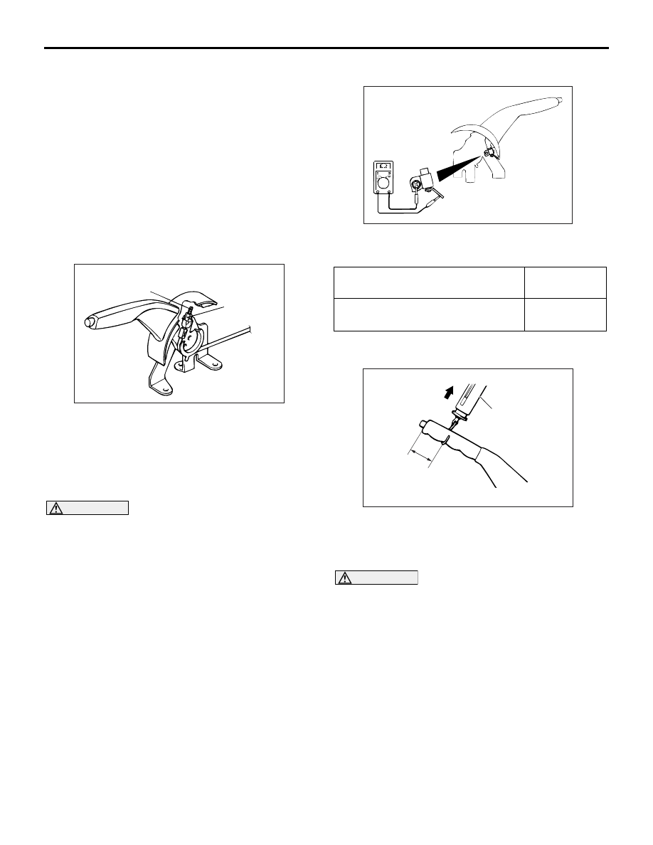
PARKING BRAKE SWITCH CHECK
M1361003300488
1. Remove the rear floor console assembly (Refer to
GROUP 52A, Rear Floor Console
2. Remove the front seat assembly (RH) (Refer to
GROUP 52A, Front Seat
AC006198AB
3. Check for continuity between the parking brake
switch terminal and the switch mounting bolt.
When parking brake lever is pulled Less than 2
ohms
When parking brake lever is
released
Open circuit
LINING RUNNING-IN
M1361001100336
AC212035AB
Spring balance
Approximately
40 mm
Pull
Carry out running-in by the following procedure when
replacing the parking brake linings or the rear brake
disc rotors, or when brake performance is insuffi-
cient.
CAUTION
Carry out running-in a place with good visibility,
and pay careful attention to safety.
1. Adjust the parking brake stroke to the standard
value.
Standard value (Operation force: Approxi-
mately 200 N): 5 - 7 notches
2. Hook a spring balance onto the centre of the
parking brake lever grip and pull it with a force of
100
− 150 N in a direction perpendicular to the
handle.
3. Drive the vehicle at a constant speed of 35
− 50
km/h for 100 meters.
4. Release the parking brake and let the brakes cool
for 5 - 10 minutes.
5. Repeat the procedure in steps 2 to 4, four or five
times.

PARKING BRAKE LEVER
PARKING BRAKES
36-4
PARKING BRAKE LEVER
REMOVAL AND INSTALLATION
M1361001300426
Pre-removal Operation
Rear Floor Console Assembly and Rear Console Bracket
Removal (Refer to GROUP 52A, Rear Floor Console
).
Post-installation Operation
• Parking Brake Lever Stroke Adjustment (Refer to
• Rear Floor Console Assembly and Rear Console Bracket
Installation (Refer to GROUP 52A, Rear Floor Console
).
AC212036
3
2
5
1
4
AB
AC212037
ABC
AB
Ratchet plate
Ratchet pawl
A
A
B
B
Section A - A
Section B - B
Removal steps
1.
Adjusting nut
2.
Parking brake switch connector
3.
Parking brake cable connection
4.
Parking brake lever assembly
5.
Parking brake switch
Removal steps (Continued)
Нет комментариевНе стесняйтесь поделиться с нами вашим ценным мнением.
Текст