Mitsubishi Lancer Evolution IX. Manual — part 609

TROUBLESHOOTING <ACD>
MANUAL TRANSMISSION (FF)
22A-119
SYMPTOM PROCEDURES
INSPECTION PROCEDURE 1: No communication possible between M.U.T.-II/III and all systems
FUSIBLE
LINK
IGNITION
SWITCH (IG2)
POWER
SOURCE
4WD-ECU
DIAGNOSIS
CONNECTOR
1
Diagnosis connector circuit <LH drive vehicles>
Wire colour code
B : Black LG : Light green
G : Green L : Blue
W : White Y : Yellow
SB : Sky blue BR : Brown
O : Orange GR : Gray
R : Red P : Pink V : Violet

TROUBLESHOOTING <ACD>
MANUAL TRANSMISSION (FF)
22A-120
OPERATION
The M.U.T.-II/III is energised by connecting the diag-
nosis connector.
COMMENTS ON TROUBLE SYMPTOM
The diagnosis connector power supply circuit, earth
circuit, or M.U.T.-II/III may be faulty.
PROBABLE CAUSES
• Malfunction of diagnosis connector
• Damaged harness wires and connectors
• Malfunction of the 4WD-ECU
FUSIBLE
LINK
IGNITION
SWITCH (IG2)
POWER
SOURCE
4WD-ECU
DIAGNOSIS
CONNECTOR
1
Diagnosis connector circuit <RH drive vehicles>
Wire colour code
B : Black LG : Light green
G : Green L : Blue
W : White Y : Yellow
SB : Sky blue BR : Brown
O : Orange GR : Gray
R : Red P : Pink V : Violet

TROUBLESHOOTING <ACD>
MANUAL TRANSMISSION (FF)
22A-121
DIAGNOSIS
STEP 1. Measure the voltage at diagnosis
connector C-14.
Measure the voltage between diagnosis connector
C-14 terminal No.16 and earth.
OK: System voltage
Q: Is the check result normal?
YES :
Go to Step 4.
NO :
Go to Step 2.
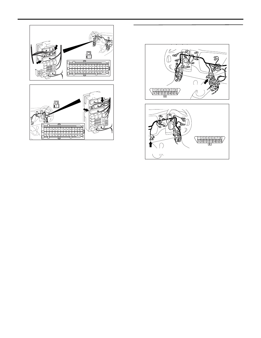
STEP 2. Connectors check: C-14 diagnosis
connector, C-126 intermediate connector, C-212,
C-214 J/B connector.
AC311015AM
Connector: C-14 <LH drive vehicles>
C-14 (B)
C-14
AC311037
C-14 (B)
AE
Connector: C-14 <RH drive vehicles>
C-14
AC311015AM
Connector: C-14 <LH drive vehicles>
C-14 (B)
C-14
AC311037
C-14 (B)
AE
Connector: C-14 <RH drive vehicles>
C-14
AC311015AN
Connector: C-126 <LH drive vehicles>
C-126
C-126
AC311016AI
Connector: C-126 <RH drive vehicles>
C-126
C-126
TROUBLESHOOTING <ACD>
MANUAL TRANSMISSION (FF)
22A-122
Check for the contact with terminals.
Q: Is the check result normal?
YES :
Go to Step 3.
NO :
Repair the defective connector.
STEP 3. Check the harness between diagnosis
connector C-14 terminal No.16 and fusible link
No.1.
Check the power supply line for short or open circuit.
Q: Is the check result normal?
YES :
Intermittent malfunction (Refer to GROUP
00
− How to Cope with Intermittent
).
NO :
Repair the wiring harness.
AC310448
AV
Connector: C-212, C-214 <LH drive vehicles>
Junction block (front view)
C-214
C-212 (B)
C-212
C-214
AC310458
AR
Connector: C-212,
C-214 <RH drive vehicles>
Junction block (front view)
C-214
C-212 (B)
C-212
C-214
AC311015AM
Connector: C-14 <LH drive vehicles>
C-14 (B)
C-14
AC311037
C-14 (B)
AE
Connector: C-14 <RH drive vehicles>
C-14
Нет комментариевНе стесняйтесь поделиться с нами вашим ценным мнением.
Текст