Mitsubishi Lancer Evolution IX. Manual — part 151

SYMPTOM PROCEDURES
SMART WIRING SYSTEM (SWS) NOT USING SWS MONITOR
54B-167
Step 3. Pulse check
Check the input signals below, which are related to
the headlamp automatic shutdown function.
OK: The M.U.T.-II/III sounds or the voltmeter
needle fluctuates.
Q: Is the check result normal?
All the signals are received normally. :
Go to Step
4.
The ignition switch (IG1) signal is not received. :
Refer to inspection procedure L-2 "The
ignition switch (IG1) signal is not received
."
The driver's door switch signal is not received. :
Refer to inspection procedure L-3 "The door
switch (front: LH) signal is not received <LH
drive vehicles>
inspection procedure L-3 "The door switch
(front: RH) signal is not received <RH drive
vehicles>
The tail lamp switch signal is not received. :
Refer
to inspection procedure L-4 "The column
switch (lighting and turn-signal lamp switch)
signal is not received
Step 4. Retest the system.
Replace the ETACS-ECU, and then check that the
headlamp automatic shutdown function works nor-
mally.
(1) Replace the ETACS-ECU.
(2) Check that the headlamp automatic shutdown
function works normally.
Q: Is the check result normal?
YES :
The trouble can be an intermittent
malfunction (Refer to GROUP 00
− How to
Cope with Intermittent Malfunction
NO :
Replace the front-ECU.
System switch
Check condition
Ignition switch (IG1)
When turned from ACC
to ON
Driver's door switch
When the driver's door is
opened
Tail lamp switch
When the lighting switch
is turned to the TAIL
position

SYMPTOM PROCEDURES
SMART WIRING SYSTEM (SWS) NOT USING SWS MONITOR
54B-168
INSPECTION PROCEDURE H-6: Any of tail lamps, position lamps or licence plate lamps does not
illuminate. <LH drive vehicles>
CAUTION
Whenever the ECU is replaced, ensure that the input
and output signal circuits are normal.
FRONT-ECU
COMBINATION METER
LICENCE
PLATE
LAMP
(LH)
(RH)
Wire colour code
B : Black LG : Light green G : Green L : Blue W : White Y : Yellow SB : Sky blue
BR : Brown O : Orange GR : Gray R : Red P : Pink V : Violet
TAIL LAMP
RELAY
REAR
COMBINATION
LAMP
(TAIL: LH)
HEADLAMP
ASSEMBLY
(POSITION)
(LH)
(RH)
REAR
COMBINATION
LAMP
(TAIL: RH)
Taillamps, Position Lamps and License Plate Lamps Circuit <LHD>

SYMPTOM PROCEDURES
SMART WIRING SYSTEM (SWS) NOT USING SWS MONITOR
54B-169
COMMENTS ON TROUBLE SYMPTOM
If the tail lamps, the position lamps or the licence
plate lamps do not illuminate, the wiring harness con-
nector(s), the bulb or the fuse may be defective or
burned out.
POSSIBLE CAUSES
• Burned-out bulb
• Damaged harness wires and connectors
DIAGNOSTIC PROCEDURE
Step 1. Connector check: F-14 <tail lamp LH> or
F-08 <tail lamp RH> rear combination lamp
connector, A-31 <position lamp LH> or A-39
<position lamp RH> headlamp assembly
connector, F-11 <licence plate lamp LH> or F-10
<licence plate lamp RH> licence plate lamp
connector, C-02 <tail lamp indicator>
combination meter connector
Q: Is the check result normal?
YES :
Go to Step 2.
NO :
Repair the defective connector.
Step 2. Check the bulbs of the tail lamps, the
position lamp, the licence plate lamp or tail lamp
indicator.
Check the bulb of the lamp which does not illumi-
nate.
Q: Is the check result normal?
YES :
Go to Step 3.
NO :
Replace the bulb of the lamp which does not
illuminate.
AC310468
Connectors: F-08, F-10, F-11, F-14
<LHD>
AD
F-08(B)
F-10(GR)
F-11(GR)
F-14(B)
Harness side
F-08
Harness side
F-11
Harness side
F-10
Harness side
F-14
AC310542
Connectors: A-31
AD
A-31(B)
Harness side
A-31
<LHD>
AC310431
Connectors: A-39
AE
A-39(B)
Harness side
A-39
<LHD>
AC310446
Connector: C-02
<LHD>
AK
Harness side
31
35
36
37
38
39
40
41
45
46
47
48
49
50
51
34
44
33
43
32
42
C-02 (L)
SYMPTOM PROCEDURES
SMART WIRING SYSTEM (SWS) NOT USING SWS MONITOR
54B-170
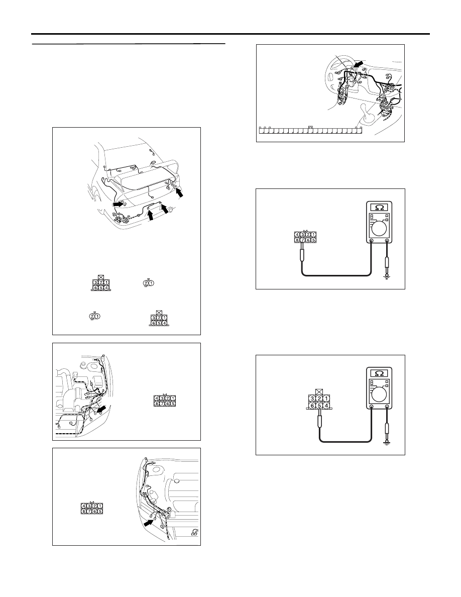
Step 3. Resistance measurement at the F-14 <tail
lamp LH> or F-08 <tail lamp RH> rear
combination lamp connector, the A-31 <position
lamp LH> or A-39 <position lamp RH> headlamp
assembly connector, the F-11 <licence plate lamp
LH> or F-10 <licence plate lamp RH> licence
plate lamp connector or C-02 <tail lamp
indicator> combination meter connector
(1) Disconnect the connector, and measure at the
wiring harness side.
(2) Check the resistance between the lamp
connector and body earth.
•
Resistance between A-31 <position lamp LH>
headlamp assembly connector terminal No.7
and body earth
• Resistance between A-39 <position lamp
RH> headlamp assembly connector terminal
No.7 and body earth
•
Resistance between F-14 <tail lamp LH> rear
combination lamp connector terminal No.5
and body earth
• Resistance between F-08 <tail lamp RH> rear
combination lamp connector terminal No.5
and body earth
AC310468
Connectors: F-08, F-10, F-11, F-14
<LHD>
AD
F-08(B)
F-10(GR)
F-11(GR)
F-14(B)
Harness side
F-08
Harness side
F-11
Harness side
F-10
Harness side
F-14
AC310542
Connectors: A-31
AD
A-31(B)
Harness side
A-31
<LHD>
AC310431
Connectors: A-39
AE
A-39(B)
Harness side
A-39
<LHD>
AC310446
Connector: C-02
<LHD>
AK
Harness side
31
35
36
37
38
39
40
41
45
46
47
48
49
50
51
34
44
33
43
32
42
C-02 (L)
AC301541HP
Connector A-31, A-39
(Harness side)
AC301541HN
Connector F-08, F-14
(Harness side)
Нет комментариевНе стесняйтесь поделиться с нами вашим ценным мнением.
Текст