Mitsubishi Lancer Evolution IX. Manual — part 167

SYMPTOM PROCEDURES
SMART WIRING SYSTEM (SWS) NOT USING SWS MONITOR
54B-231
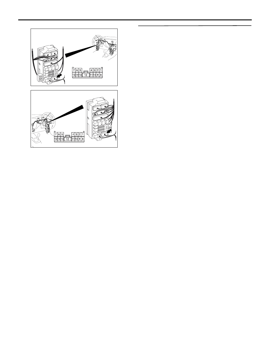
Step 14. Connector check: C-226 ETACS-ECU
connector
Q: Is the check result normal?
YES :
Go to Step 15.
NO :
Repair the defective connector.
Step 15. Check the wiring harness from C-226
ETACS-ECU connector terminal No.6 to F-02
luggage compartment lamp connector terminal
No.1.
AC310450
Connector: C-226
AB
Junction block side
Junction block (rear view)
<LHD>
AC310461
Junction block (rear view)
Connector: C-226
AB
<RHD>
Junction block side
AC310450
Connector: C-226
AB
Junction block side
Junction block (rear view)
<LHD>
AC310461
Junction block (rear view)
Connector: C-226
AB
<RHD>
Junction block side
AC310467
Connector: F-02
Harness side
AB
<LHD>
AC310469
Connector: F-02
Harness side
AB
<RHD>
SYMPTOM PROCEDURES
SMART WIRING SYSTEM (SWS) NOT USING SWS MONITOR
54B-232
NOTE:
Prior to the wiring harness inspection, check junction
block connector C-217, and repair if necessary.
• Check the power supply line for open circuit.
Q: Is the check result normal?
YES :
Go to Step 16.
NO :
Repair the wiring harness.
Step 16. Retest the system.
Check that the luggage compartment lamp illumi-
nates and extinguishes normally.
Q: Is the check result normal?
YES :
The trouble can be an intermittent
malfunction (Refer to GROUP 00
− How to
Cope with Intermittent Malfunction
NO :
Replace the ETACS-ECU.
AC310448
Harness side
Junction block (front view)
Connector: C-217
AC
<LHD>
AC310458
Harness side
Junction block (front view)
Connector: C-217
AC
<RHD>

SYMPTOM PROCEDURES
SMART WIRING SYSTEM (SWS) NOT USING SWS MONITOR
54B-233
INSPECTION PROCEDURE K-2: Interior lamp automatic shutdown function does not work normally.
CAUTION
Whenever the ECU is replaced, ensure that the
input and output signal circuits are normal.
COMMENTS ON TROUBLE SYMPTOM
The ETACS-ECU operates the interior lamp auto-
matic shutdown function in accordance with the input
signals below.
• Ignition switch (ACC)
• Ignition switch (IG1)
• Driver's door switch
• All of the door switches
• Interior lamp loaded signal
If this function does not work normally, these input
signal circuit(s) or the ETACS-ECU may be defec-
tive. Note that this function can be disabled/enabled
by the adjustment function (default setting; enabled).
POSSIBLE CAUSES
• Malfunction of the door switches
• Malfunction of the room lamp
• Malfunction of the ETACS-ECU
• Damaged harness wires and connectors
DIAGNOSTIC PROCEDURE
Step 1. Check the adjustment function.
Check that the interior lamp automatic shutdown
function has been enabled by using the adjustment
function.
Q: Is the check result normal?
YES :
Go to Step 2.
NO :
Enable the interior lamp automatic
shutdown function by using the adjustment
function. Refer to
INPUT SIGNAL
COMBINATION
METER
KEEP RELAY
LOAD
DETERMINATION
CIRCUIT
LOAD
DETERMINATION
CIRCUIT
· ALL DOOR
SWITCH
· DRIVER'S DOOR
SWITCH
· IGNITION
SWITCH (ACC)
· IGNITION
SWITCH (IG1)
· INTERIOR LAMP
LOADED SIGNAL
ETACS-ECU
· FRONT ROOM LAMP
· REAR ROOM LAMP
· LUGGAGE COMPARTMENT LAMP
J/B SIDE
RELAY BOX
(FUSE )
22
Interior Lamp Automatic Shutdown Function Circuit

SYMPTOM PROCEDURES
SMART WIRING SYSTEM (SWS) NOT USING SWS MONITOR
54B-234
Step 2. Check the power supply circuit.
When the ignition switch is turned to the LOCK
(OFF) position, check if the hazard warning lamps
illuminate.
Q: Is the check result normal?
YES :
Go to Step 3.
NO :
Refer to inspection procedure A-2 "Check
the battery power supply circuit to the
ETACS-ECU
Step 3. Pulse check
Check the input signals below, which are related to
the front and rear dome lamps.
OK: The M.U.T.-II/III sounds or the voltmeter
needle fluctuates.
Q: Is the check result normal?
All the signals are received normally. :
Go to Step
4.
The ignition switch (ACC) signal is not received. :
Refer to inspection procedure L-1 "The
ignition switch (ACC) signal is not received
."
The ignition switch (IG1) signal is not received. :
Refer to inspection procedure L-2 "The
ignition switch (IG1) signal is not received
."
The driver's door switch signal is not received. :
Refer to inspection procedure L-3 "The door
switch (front: LH) signal is not received <LH
drive vehicles>
inspection procedure L-3 "The door switch
(front: RH) signal is not received <RH drive
vehicles>
All the door switch signals are not received. :
Refer to inspection procedure L-10 "All the
door switch signals are not received <LH
drive vehicles>
inspection procedure L-10 "All the door
switch signals are not received <RH drive
vehicles>
Interior lamp loaded signal is not detected :
Refer
to inspection procedure L-15 "Interior lamp
loaded signal is not detected
Step 4. Retest the system.
Check that the interior lamp automatic shutdown
function works normally.
Q: Is the check result normal?
YES :
The trouble can be an intermittent
malfunction (Refer to GROUP 00
− How to
Cope with Intermittent Malfunction
NO :
Replace the ETACS-ECU.
System switch
Check condition
Ignition switch (ACC)
When turned from the
LOCK (OFF) position to
the ACC position
Ignition switch (IG1)
When turned from ACC
to ON
Driver's door switch
Driver's door is opened
while all the other doors
are closed.
All of the door switches
A door is opened when
all the doors are closed
Interior lamp loaded
signal
When a load is applied
through multi-purpose
fuse No.18
Нет комментариевНе стесняйтесь поделиться с нами вашим ценным мнением.
Текст