Mitsubishi Lancer Evolution IX. Manual — part 83
TIMING BELT
ENGINE OVERHAUL
11B-23
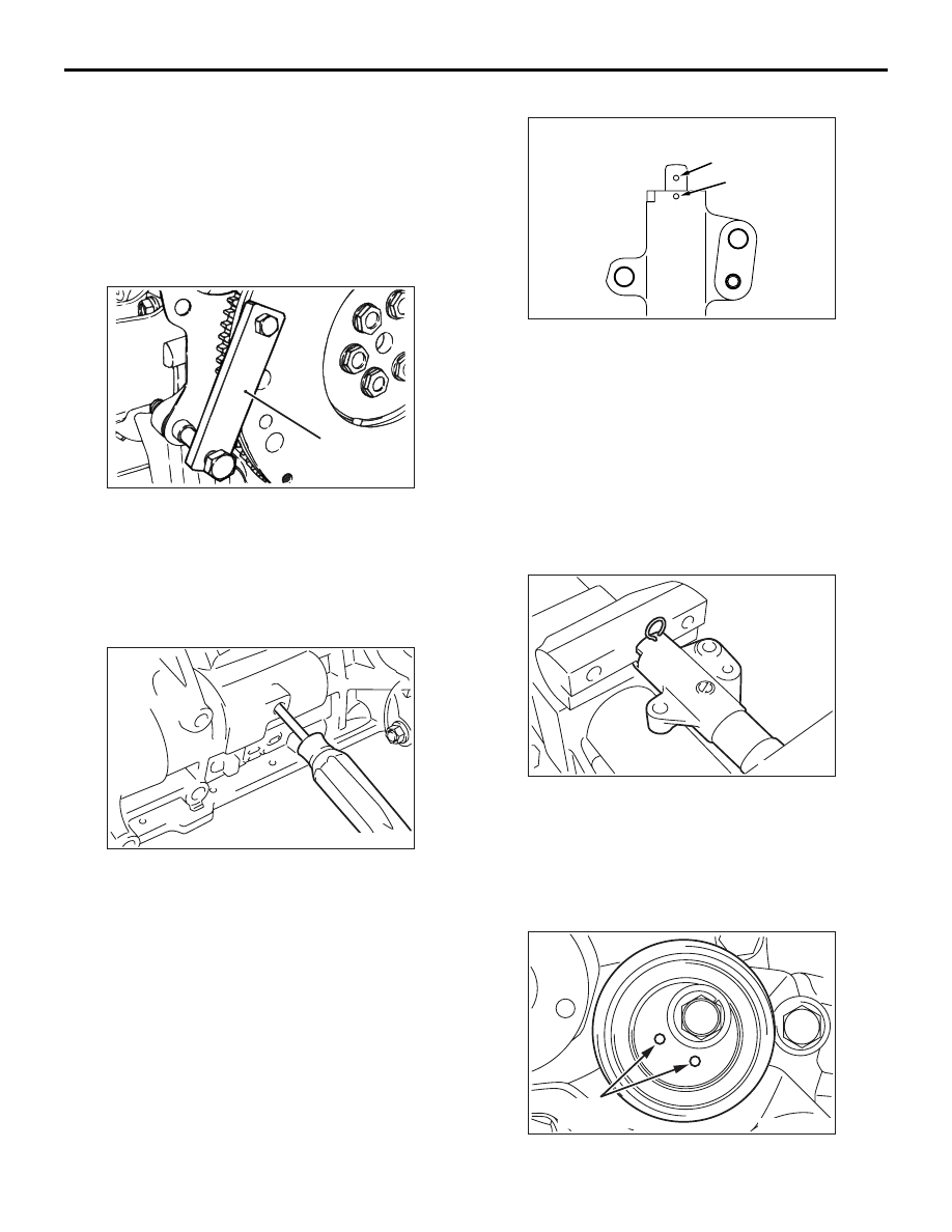
1. Clean and then degrease the crankshaft sprocket,
sprocket fitting surface of the crankshaft, and
crankshaft sensing blade. Install the crankshaft
sprocket and crankshaft sensing blade on the
crankshaft.
2. Clean the bolt hole in the crankshaft, and then
washer.
3. Apply a necessary minimum amount of oil to the
threads and seating surface of the crankshaft bolt.
4. Hold the drive plate using the special tool
Flywheel stopper (MD998781).
5. Tighten the crankshaft bolt to a torque of 167 N
⋅m.
>>I<< OIL PUMP SPROCKET
INSTALLATION
1. Prevent the counterbalancer shaft from rotating in
the same method as in the removal procedure.
2. Install the oil pump sprocket.
3. Apply a thin coat of engine oil to the seating
surface of the nut.
4. Tighten the flange nut to 54
± 5 N⋅m.
>>J<< AUTO-TENSIONER INSTALLATION
1. If the auto-tensioner rod remains in its fully
extended position, reset it to the retracted position
as follows:
(1) Clamp the auto-tensioner in a vise at right
angles to the jaws.
(2) Push in the rod little by little with the vise until
the set hole A in the rod is aligned with the set
hole "B" in the cylinder.
(3) Insert a piece of wire (1.4 mm diameter) into
the set holes.
(4) Remove the auto-tensioner from the vise.
2. Install the auto-tensioner in position. Leave the
wire installed until the auto-tensioner is
completely installed.
>>K<< TENSIONER PULLEY
INSTALLATION
Install the tensioner pulley with its holes aligned as
shown in the drawing.
AK202738
MD998781
AC
AK300172
AK301074
A
B
AD
AK300154
AK300147
Tensioner
pulley hole
AE
TIMING BELT
ENGINE OVERHAUL
11B-24
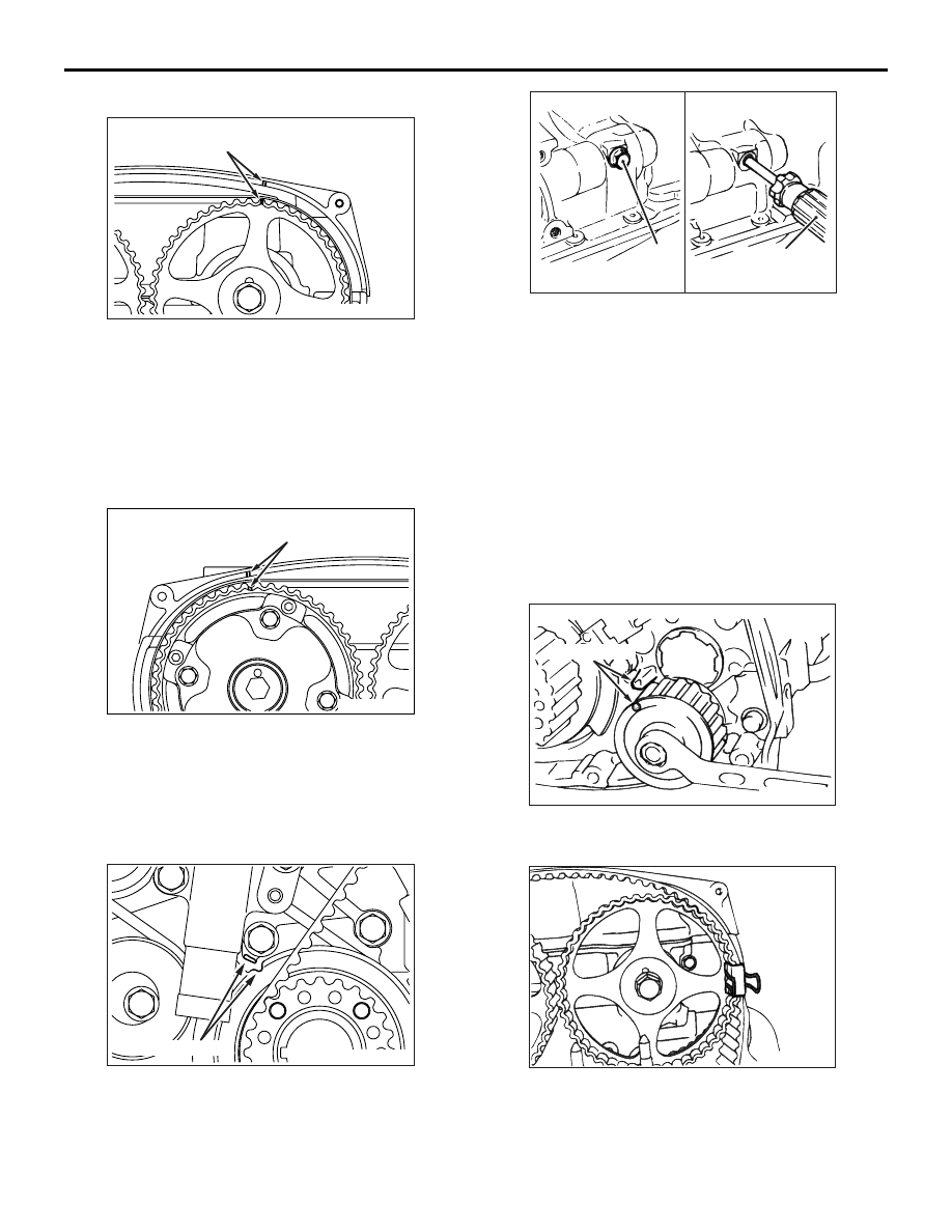
>>L<< TIMING BELT INSTALLATION
1. Bring the timing mark on the exhaust camshaft
sprocket to a point one sprocket tooth away from
the timing mark on the rocker cover in the
anti-clockwise direction.
NOTE: If the timing marks were aligned, the
exhaust camshaft would be turned anti-clockwise
by one sprocket tooth and stay there by the force
of the valve springs.
2. Align the timing mark on the intake camshaft
sprocket with that on the rocker cover.
NOTE: The intake camshaft will be turned slightly
clockwise from where the timing marks are
aligned by the force of the valve springs and stay
there.
3. Bring the timing mark on the crankshaft sprocket
to a point one sprocket tooth away from the
mating timing mark in the anti-clockwise direction
like in the operation with the exhaust camshaft
sprocket.
4. Align the timing mark on the oil pump sprocket
with that on the cylinder block.
(1) Remove the plug from the cylinder block.
(2) Insert a crosspoint screwdriver with a shank
diameter of 8 mm through the plug hole. If it
can be inserted 60 mm or more, the sprocket
is in the correct phase. If the insertion depth is
up to 20
− 25 mm, the screwdriver is blocked
by the counterbalancer shaft. Then turn the oil
pump sprocket one turn and realign the timing
marks. Then check that the screwdriver can
be inserted 60 mm or more. Keep the
screwdriver inserted until installation of timing
belt is finished.
(3) Turn the oil pump sprocket anti-clockwise by
one sprocket tooth.
5. Install the timing belt on the exhaust camshaft
sprocket, and hold it in place with a paper clip at
the point indicated in the drawing.
AK304440AB
Timing marks
AK501745
Timing marks
AB
AK304563AB
Timing marks
AK202752
Crosspoint
screwdriver
AD
Plug
AK202761
Timing marks
AD
AK202771

TIMING BELT
ENGINE OVERHAUL
11B-25
6. Turn the intake camshaft sprocket anti-clockwise
to bring the timing mark on it one sprocket tooth
away from the mating timing mark in the
anti-clockwise direction. Then install the timing
belt on the sprocket and hold it in place with a
paper clip.
NOTE: The timing marks will be aligned when the
belt is installed since the intake camshaft is turned
slightly clockwise by the force of the valve
springs.
7. Turn the exhaust camshaft sprocket clockwise to
align the timing marks, and make sure that the
intake camshaft sprocket timing marks are also
aligned.
8. Install the timing belt on the idler pulley, oil pump
sprocket, and crankshaft sprocket, in this order.
NOTE: There should be no slack in the installed
portion of the belt.
9. Install the timing belt on the tensioner pulley.
NOTE: Turning slightly the intake camshaft
sprocket anti-clockwise will facilitate installation of
the belt on the tensioner pulley.
10.Turn slightly the crankshaft sprocket clockwise to
take up the slack in the idler pulley portion of the
timing belt.
11.Check that each of the timing marks on the
crankshaft, oil pump, and exhaust camshaft
sprockets is one sprocket tooth away from its
mating timing mark in the anti-clockwise direction.
12.Turn the tensioner pulley anti-clockwise using the
special tool Tension pulley socket wrench
(MD998767) to give tension to the belt and hold
the tensioner in position by temporarily tightening
the tensioner lock bolt.
NOTE: Take up the slack in the belt portion
between the intake and exhaust camshaft sprock-
ets.
AK501746
AK501747
Timing marks
AB
AK202762AE
Crankshaft
sprocket
Oil pump
sprocket
AK501748AB
V.V.T.
sprocket
Tensioner
pulley
AK202763AB
Crankshaft
sprocket
AK202764
MD998767
AD

TIMING BELT
ENGINE OVERHAUL
11B-26
13.Turn the crankshaft clockwise to make the timing
mark align with the No.1 cylinder top dead centre
mark.
14.Install the special tool Set screw (MD998738) and
turn down the tool until the wire (inserted in the
auto-tensioner when it was installed) can be
moved freely.
15.Loosen the tensioner pulley lock bolt.
CAUTION
Prevent the timing belt from slipping as it
becomes loose following rotation of the intake
and exhaust camshafts.
16.Turn the torque wrench attached to the special
tool Tension pulley socket wrench (MD998767)
anti-clockwise until the slack in the timing belt is
taken up.
17.Turn the torque wrench clockwise from the
position of step 16 until the torque wrench reading
becomes 3.5 N
⋅m, then tighten the tensioner
pulley lock bolt.
18.Remove the special tool Set screw (MD998738)
that was installed in step 14.
19.Turn the crankshaft clockwise two turns, then let it
alone for approx. 15 minutes.
20.Check that the wire (inserted in the auto-tensioner
when it was installed) can be moved freely. If the
wire can be pulled freely, the belt tensioner is
adjusted properly. Remove the wire. At that time,
check that the auto-tensioner rod extends by the
specified amount.
Standard value: 3.8
− 4.5 mm
CAUTION
Be sure to check the tightening torque of the
crankshaft bolt anytime the crankshaft has been
turned anti-clockwise. If the torque lower than
specification, tighten the bolt to the specified
torque.
21.If the wire cannot be pulled out freely, perform the
steps 14 through 18 again to make the belt
tension proper.
>>M<< PLUG CAP INSTALLATION
CAUTION
Do not reuse the washer.
1. Install the washer to the plug cap.
2. Holding the hexagonal portion of the camshaft
with a wrench, tighten the plug cap to the
specified torque of 32
± 2 N⋅m.
AK202774
MD998738
AD
AK202775
MD998767
AD
AK202829
Extension
amount
AB
AK403836
Нет комментариевНе стесняйтесь поделиться с нами вашим ценным мнением.
Текст