Mitsubishi Lancer Evolution IX. Manual — part 430

TROUBLESHOOTING
MULTIPORT FUEL INJECTION (MPI)
13A-195
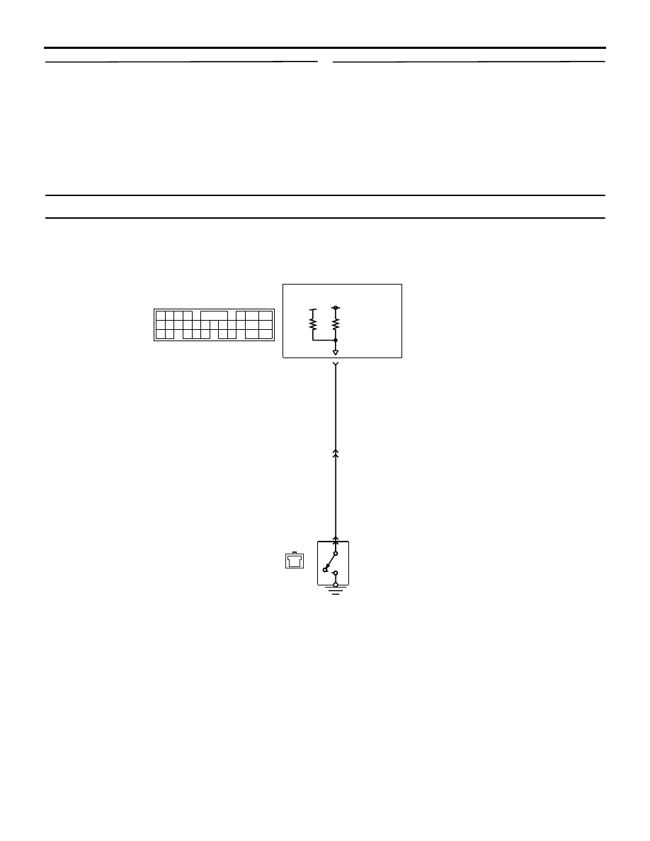
Code No. P0513: Immobilizer System
OPERATION
• The signals are sent and received between
engine-ECU (terminal No. 98) and immobi-
lizer-ECU (terminal No. 7).
FUNCTION
• Engine-ECU sends or receives the control sig-
nals to or from immobilizer-ECU to certify the
ignition key.
NOTE:
.
•
If the registered ignition keys are close each
other when starting the engine, radio interfer-
ence may cause this code to be displayed.
•
This code may be displayed when registering
the key encrypted code.
TROUBLE JUDGMENT
Check Condition
• Ignition switch: "ON"
Judgment Criterion
• When the communication error between the
engine-ECU and the immobilizer-ECU continues
for 2 seconds or more.
PROBABLE CAUSES
• Open/short circuit in immobilizer system circuit or
loose connector contact
• Failed immobilizer-ECU
• Failed engine-ECU
1
2
3 4 5 6 7
AK501818
2
1
3 4
80
87
81
94
85
82
84
93
86
98
99
74
92
73
83
88
91
95
97
96
100
89
78
71
90
76 77
75
72
79
3
98
7
21
C-207
MU801547
C-117
(MU803783)
Engine-ECU
Immobilizer system circuit
Immobilizer-ECU
GR
R-W
C-207-1
C-207-1
Wire colour code
B: Black LG: Light green G: Green L: Blue W: White Y: Yellow SB: Sky blue BR: Brown O: Orange GR: Gray
R: Red P: Pink V: Violet PU: Purple
AB
C-124
TROUBLESHOOTING
MULTIPORT FUEL INJECTION (MPI)
13A-196
DIAGNOSIS PROCEDURE
STEP 1. Connector check: C-207
immobilizer-ECU connector and C-117
engine-ECU connector
Q: Is the check result normal?
YES :
Go to Step 2 .
NO :
Repair or replace the connector.
STEP 2. Check harness between C-207 (terminal
No. 7) immobilizer-ECU connector and C-117
(terminal No. 98) engine-ECU connector.
NOTE: Before checking harness, check intermediate
connector C-124, and repair if necessary.
• Check output line for open/short circuit and dam-
age.
Q: Is the check result normal?
YES :
Go to Step 3 .
NO :
Repair the damaged harness wire.
AK305030
2
1
7 6 5 4 3
AB
Connector : C-207
Harness side
connector
C-207
AK501996
80
87
81
94
85
82
84
93
86
98
99
74
92
73
83
88
91
95
97 96
100
89
78
71
90
76
77
75
72
79
AB
Connector: C-117
C-117 (GR)
C-117 (GR)
Harness side connector
<L. H. drive vehicles>
<R. H. drive vehicles>
AK305030
2
1
7 6 5 4 3
AB
Connector : C-207
Harness side
connector
C-207
AK501996
80
87
81
94
85
82
84
93
86
98
99
74
92
73
83
88
91
95
97 96
100
89
78
71
90
76
77
75
72
79
AB
Connector: C-117
C-117 (GR)
C-117 (GR)
Harness side connector
<L. H. drive vehicles>
<R. H. drive vehicles>
TROUBLESHOOTING
MULTIPORT FUEL INJECTION (MPI)
13A-197
STEP 3. Check the trouble symptoms.
Q: Does trouble symptom persist?
YES :
Go to Step 4 .
NO :
Intermittent malfunction (Refer to GROUP
00
− How to Use
Troubleshooting/Inspection Service Points
).
STEP 4. Replace the immobilizer-ECU.
• After replacing the immobilizer-ECU, re-check the
trouble symptoms.
Q: Does trouble symptom persist?
YES :
Replace the engine-ECU.
NO :
The check is end.
Code No. P0551: Power Steering Fluid Pressure Switch System
CONDITION
• The battery voltage is applied to the power steer-
ing fluid pressure switch (terminal No. 1) from the
engine-ECU (terminal No. 54).
AK501819
1
65
43
50
42
49
41
48
60 61
64
46 47
58 59
67 68
45
56
66
52
51
44
53
62
54
63
57
55
R-W
R-W
54
Power steering fluid
pressure switch
A-40
1
Power steering fluid pressure switch circuit
C-119
(MU803782)
Engine-ECU
5 <A-13> (*1) or
15 <C-31> (*2)
Wire colour code
B: Black LG: Light green G: Green L: Blue W: White Y: Yellow SB: Sky blue BR: Brown O: Orange GR: Gray
R: Red P: Pink V: Violet PU: Purple
NOTE
*1: L.H. drive vehicles
*2: R.H. drive vehicles
AB

TROUBLESHOOTING
MULTIPORT FUEL INJECTION (MPI)
13A-198
FUNCTION
• It is detected whether a load is applied on the
power steering fluid pump by steering or not, and
the signal is inputted to the engine-ECU. When
the power steering fluid pressure switch "ON" sig-
nal (a large load on the power steering fluid
pump) is inputted, the engine-ECU provides the
idle-up control.
TROUBLE JUDGMENT
Check Conditions
• The engine coolant temperature is 30°C or
higher.
• Drive for 4 seconds or more with the vehicle
speed is 50 km/h or more. Stop the vehicle (vehi-
cle speed is 1.5 km/h or less). Repeat 10 times is
more.
Judgment Criterion
• The power steering fluid pressure switch remains
in "ON" position.
PROBABLE CAUSES
• Failed power steering fluid pressure switch
• Open/short circuit in power steering fluid pres-
sure switch circuit or loose connector contact
• Failed engine-ECU
DIAGNOSIS PROCEDURE
NOTE:
.
*1: L.H. drive vehicles
*2: R.H. drive vehicles
STEP 1. Connector check: A-40 power steering
fluid pressure switch connector
Q: Is the check result normal?
YES :
Go to Step 2 .
NO :
Repair or replace the connector.
STEP 2. Perform voltage measurement at A-40
power steering fluid pressure switch connector.
• Disconnect connector, and measure at harness
side.
• Ignition switch: "ON"
• Voltage between terminal No. 1 and earth.
OK: System voltage
Q: Is the check result normal?
YES :
Go to Step 8 .
NO :
Go to Step 3 .
1
AK502001AB
Connector: A-40
Harness side
connector
A-40 (B)
1
AK502001AB
Connector: A-40
Harness side
connector
A-40 (B)
Нет комментариевНе стесняйтесь поделиться с нами вашим ценным мнением.
Текст