Mitsubishi Lancer Evolution IX. Manual — part 159
SYMPTOM PROCEDURES
SMART WIRING SYSTEM (SWS) NOT USING SWS MONITOR
54B-199
DIAGNOSTIC PROCEDURE
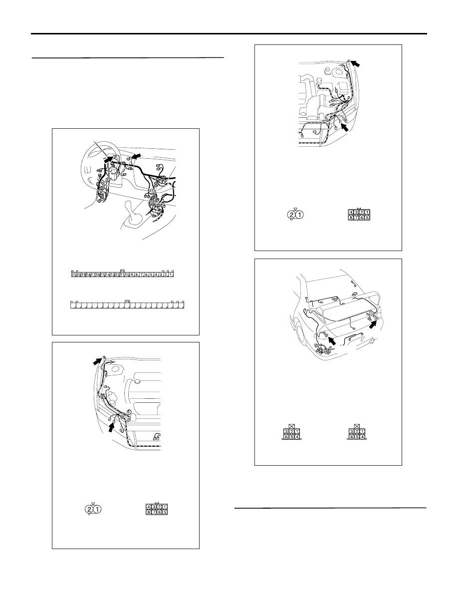
Step 1. Connector check: A-39 <front RH> or
A-31 <front LH> headlamp assembly connector,
A-01 <side RH> or A-02 <side LH> side
turn-signal lamp connector, F-08 <rear RH> or
F-14 <rear LH> rear combination lamp connector,
C-02 <turn-signal indicator lamp> and C-01
<turn-signal indicator lamp (LH)> combination
meter connector
Q: Is the check result normal?
YES :
Go to Step 2.
NO :
Repair the defective connector.
Step 2. Check the bulb(s) of the turn-signal lamps
or the turn-signal indicator lamps.
Check the bulb(s) of the defective lamp.
Q: Is the check result normal?
YES :
Go to Step 3.
NO :
Replace the bulb(s) of the defective lamp.
AC310447
Connectors: C-01, C-02
AE
<LHD>
C-01
Harness side
C-02
Harness side
31
32
33
34
35
36
37
38
39
40
41
42
43
44
45
46
47
48
49
50
51
C-01
C-02(L)
AC310432
Connectors: A-01, A-39
<LHD>
A-39
A-01 (GR)
Harness side
A-01
Harness side
A-39
AB
AC310543
Connectors: A-02, A-31
<LHD>
A-31
A-02 (GR)
Harness side
A-02
Harness side
A-31
AB
AC310468
Connectors: F-08, F-14
<LHD>
F-14
F-08
Harness side
F-08
Harness side
F-14
AC
SYMPTOM PROCEDURES
SMART WIRING SYSTEM (SWS) NOT USING SWS MONITOR
54B-200
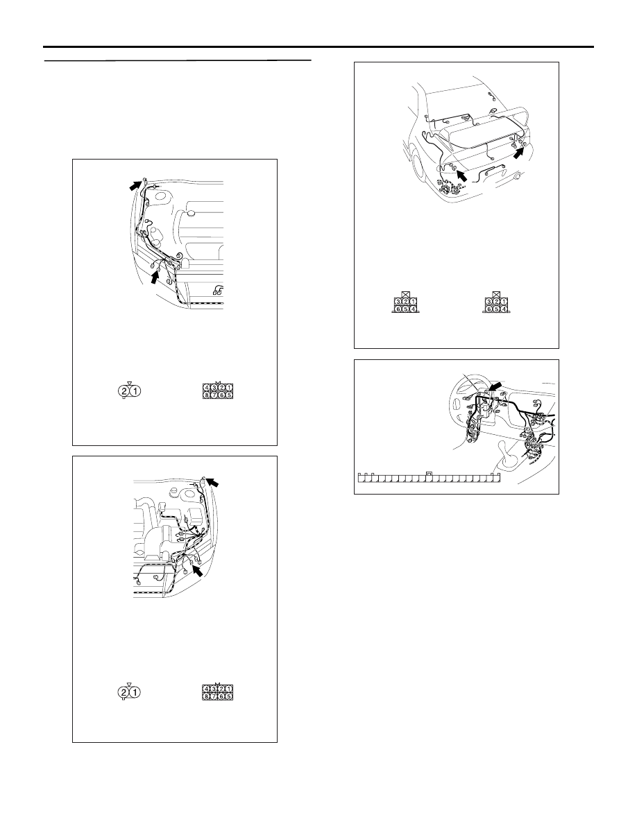
Step 3. Resistance measurement at the A-39
<front RH> or A-31 <front LH> headlamp
assembly connector, the A-01 <side RH> or A-02
<side LH> side turn-signal lamp connector, the
F-08 <rear RH> or F-14 <rear LH> rear
combination lamp connector, the C-02
<turn-signal indicator lamp> combination meter
connector
(1) Disconnect the connector, and measure at the
wiring harness side.
AC310432
Connectors: A-01, A-39
<LHD>
A-39
A-01 (GR)
Harness side
A-01
Harness side
A-39
AB
AC310543
Connectors: A-02, A-31
<LHD>
A-31
A-02 (GR)
Harness side
A-02
Harness side
A-31
AB
AC310468
Connectors: F-08, F-14
<LHD>
F-14
F-08
Harness side
F-08
Harness side
F-14
AC
AC310446
Connector: C-02
<LHD>
AK
Harness side
31
35
36
37
38
39
40
41
45
46
47
48
49
50
51
34
44
33
43
32
42
C-02 (L)

SYMPTOM PROCEDURES
SMART WIRING SYSTEM (SWS) NOT USING SWS MONITOR
54B-201
(2) Measure the resistance between the defective
lamp connector terminal and body earth.
•
Resistance between A-39 <front RH> headlamp
assembly connector terminal No.7 and body
earth
• Resistance between A-31 <front LH> head-
lamp assembly connector terminal No.7 and
body earth
•
Resistance between A-01 <side RH> side
turn-signal lamp connector terminal No.1 and
body earth
• Resistance between A-02 <side LH> side
turn-signal lamp connector terminal No.1 and
body earth
•
Resistance between F-08 <rear RH> rear combi-
nation lamp connector terminal No.5 and
body earth
• Resistance between F-14 <rear LH> rear
combination lamp connector terminal No.5
and body earth
•
Resistance between C-02 <turn-signal indicator
lamp> combination meter terminal No.48 and
body earth
OK: 2
Ω or less
Q: Is the check result normal?
YES :
Go to Step 5.
NO :
Go to Step 4.
AC301541HG
Connector A-31, A-39
(Harness side)
AC301541HH
Connector A-01, A-02
(Harness side)
AC301541HI
Connector F-08, F-14
(Harness side)
AC301541HE
Connector C-02
(Harness side)
31
35
36
37
38
39
40
41
45
46
47
48
49
50
51
34
44
33
43
32
42

SYMPTOM PROCEDURES
SMART WIRING SYSTEM (SWS) NOT USING SWS MONITOR
54B-202
Step 4. Check the wiring harness from A-39
<front RH> or A-31 <front LH> headlamp
assembly connector terminal No.7, A-01 <side
RH> or A-02 <side LH> side turn-signal lamp
connector terminal No.1, F-08 <rear RH> or F-14
<rear LH> rear combination lamp connector
terminal No.5, or C-02 <turn-signal indicator
lamp> combination meter connector terminal
No.48 to body earth.
• Check the earth wires for open circuit.
Q: Is the check result normal?
YES :
The trouble can be an intermittent
malfunction (Refer to GROUP 00
− How to
Cope with Intermittent Malfunction
NO :
Repair the wiring harness.
Step 5. Connector check: C-226 ETACS-ECU
connector
Q: Is the check result normal?
YES :
Go to Step 6.
NO :
Repair the defective connector.
AC310432
Connectors: A-01, A-39
<LHD>
A-39
A-01 (GR)
Harness side
A-01
Harness side
A-39
AB
AC310543
Connectors: A-02, A-31
<LHD>
A-31
A-02 (GR)
Harness side
A-02
Harness side
A-31
AB
AC310468
Connectors: F-08, F-14
<LHD>
F-14
F-08
Harness side
F-08
Harness side
F-14
AC
AC310446
Connector: C-02
<LHD>
AK
Harness side
31
35
36
37
38
39
40
41
45
46
47
48
49
50
51
34
44
33
43
32
42
C-02 (L)
AC310450
Connector: C-226
AB
Junction block side
Junction block (rear view)
<LHD>
Нет комментариевНе стесняйтесь поделиться с нами вашим ценным мнением.
Текст