Mitsubishi Lancer Evolution IX. Manual — part 113
DIAGNOSTIC TROUBLE CODE PROCEDURES
SMART WIRING SYSTEM (SWS) NOT USING SWS MONITOR
54B-15
DIAGNOSTIC TROUBLE CODE PROCEDURES
Diagnosis code 11: Trouble related to the ETACS-ECU
DIAGNOSIS CODE SET CONDITIONS
The ETACS-ECU monitors the data, which the ECU
itself sends. If errors occur consecutively 15 times
(for 0.6 seconds), a diagnosis code will be set. Then,
if the data does not contain any errors consecutively
15 times (for 0.6 seconds), the ECU will stop sending
the diagnosis code.
POSSIBLE CAUSES
• Malfunction of the ETACS-ECU
DIAGNOSTIC PROCEDURE
Check whether the diagnosis code is reset.
(1) Erase the diagnosis code.
(2) Again check that diagnosis code No.11 is set.
Q: Is diagnosis code No.11 set?
YES :
Replace the ETACS-ECU.
NO :
The trouble can be an intermittent
malfunction (Refer to GROUP 00
− How to

DIAGNOSTIC TROUBLE CODE PROCEDURES
SMART WIRING SYSTEM (SWS) NOT USING SWS MONITOR
54B-16
Diagnosis code 12: Trouble related to the column switch or improper connection to the ETACS-ECU
CAUTION
Whenever the ECU is replaced, ensure that the
power supply circuit, the earthing circuit and the
communication circuit are normal.
BATTERY
IGNITION
SWITCH (IG1)
COLUMN
SWITCH
Wire colour code
B : Black
LG : Light green
G : Green
L: Blue
W : White
Y: Yellow
SB : Sky blue
BR : Brown
O : Orange
GR : Gray
R : Red
P : Pink
V : Violet
COLUMN-ECU
ETACS-ECU
RELAY
BOX
LHD
RHD
LHD
RHD
NOTE
: LHD
: RHD
Column Switch Power Supply and SWS Communication Circuit
DIAGNOSTIC TROUBLE CODE PROCEDURES
SMART WIRING SYSTEM (SWS) NOT USING SWS MONITOR
54B-17
DIAGNOSIS CODE SET CONDITIONS
If the column switch ignores the data request signal
sent by the ETACS-ECU (three times or more for one
second), this diagnosis code will be set. Then, when
the column switch observes the request signal for
one second, the ECU will stop sending the diagnosis
code.
POSSIBLE CAUSES
• Malfunction of the column switch
• Malfunction of the ETACS-ECU
• Damaged harness wires and connectors
DIAGNOSTIC PROCEDURE
Step 1. M.U.T.-II/III diagnosis code.
(1) Ignition switch: ON
(2) On completion, check that diagnosis code No.12
is not reset.
Q: Is diagnosis code No.12 set?
YES :
Go to Step 5.
NO :
Go to Step 2.
Step 2. Connector check: C-206 column switch
connector
Q: Is the check result normal?
YES :
Go to Step 3.
NO :
Repair the defective connector.
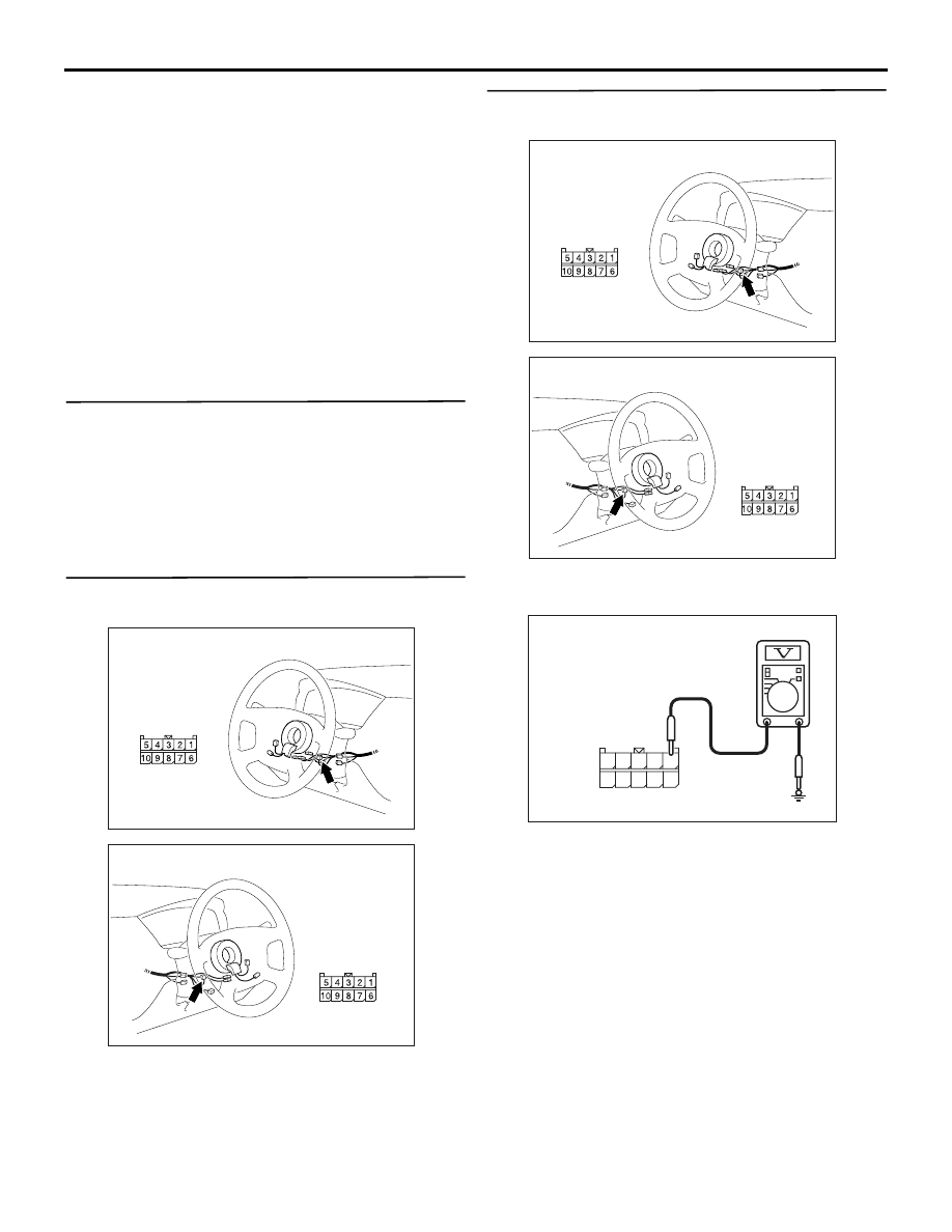
Step 3. Voltage measurement at C-206 column
switch connector
(1) Disconnect the column switch connector, and
measure at the wiring harness side.
(2) Voltage between C-206 column switch connector
terminal No.1 and body earth
OK: System voltage
Q: Is the check result normal?
YES :
Replace the column switch.
NO :
Go to Step 4.
AC310479
AD
Connector: C-206 <LHD>
Harness side
AC310481AD
Connector: C-206 <RHD>
Harness side
AC310479
AD
Connector: C-206 <LHD>
Harness side
AC310481AD
Connector: C-206 <RHD>
Harness side
AC301541HQ
Connector C-206
(Harness side)
10
5
6
7
9 8
3
4
2 1

DIAGNOSTIC TROUBLE CODE PROCEDURES
SMART WIRING SYSTEM (SWS) NOT USING SWS MONITOR
54B-18
Step 4. Check the wiring harness between C-206
column switch connector terminal No.1 and the
battery.
NOTE:
Prior to the wiring harness inspection, check interme-
diate connector C-129 and joint connector C-05, and
repair if necessary.
• Check the power supply line for open circuit.
Q: Is the check result normal?
YES :
The trouble can be an intermittent
malfunction (Refer to GROUP 00
− How to
Cope with Intermittent Malfunction
NO :
Repair the wiring harness.
AC310479
AD
Connector: C-206 <LHD>
Harness side
AC310481AD
Connector: C-206 <RHD>
Harness side
AC310447
Connectors: C-05, C-129 <LHD>
C-05 (GR)
C-129
C-05
C-129
AC
AC310455
Connectors: C-05, C-129 <RHD>
C-05 (GR)
C-129
C-05
C-129
AB
Нет комментариевНе стесняйтесь поделиться с нами вашим ценным мнением.
Текст