Mitsubishi Lancer Evolution IX. Manual — part 380
DOOR MIRROR
EXTERIOR
51-33
Q: Is the check result normal?
YES :
Go to Step 14.
NO :
Go to Step 12.
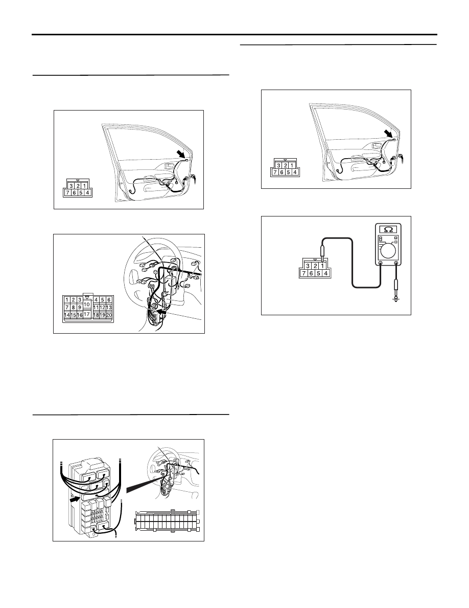
STEP 12. Check the wiring harness between E-03
door mirror assembly (LH) connector terminal
No.4 and body earth.
AC304818
Connector: E-03
Harness side
AC
• Check the earth wires for open circuit.
NOTE:
AC304820
Connector: C-17
AC
Prior to the wiring harness inspection, check interme-
diate connector C-17 and repair if necessary.
Q: Is the check result normal?
YES :
Intermittent malfunction (Refer to GROUP
00
− How to Cope with Intermittent
NO :
Repair the wiring harness.
STEP 13. Connector check: C-214 junction block
connector
AC304913
21
7
16 15
17
18
20 19
1
2
3
4
5
6
23 22
24
25
28
26
27
9
8
10
11
14
12
13
Connector: C-214
Harness side
AD
Junction block (Front view)
Q: Is the check result normal?
YES :
Go to Step 14.
NO :
Repair the defective connector.
STEP 14. Measure the voltage at the E-03 door
mirror assembly (LH) connector.
(1) Turn the ignition switch to the ON position.
(2) Rear window defogger switch: ON
AC304818
Connector: E-03
Harness side
AC
(3) Disconnect the connector, and measure at the
wiring harness side.
AC304828
Connector E-03
(harness side)
AC
(4) Voltage between E-03 door mirror assembly
connector terminal No.1 and body earth
OK: System voltage
Q: Is the check result normal?
YES :
Intermittent malfunction (Refer to GROUP
00
− How to Cope with Intermittent
).
NO :
Go to Step 15.
DOOR MIRROR
EXTERIOR
51-34
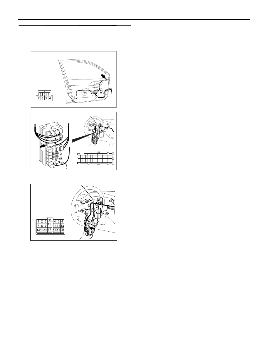
STEP 15. Check the wiring harness between E-03
door mirror assembly (LH) connector terminal
No.1 and C-214 junction block connector
terminal No.3.
AC304818
Connector: E-03
Harness side
AC
AC304913
21
7
16 15
17
18
20 19
1
2
3
4
5
6
23 22
24
25
28
26
27
9
8
10
11
14
12
13
Connector: C-214
Harness side
AD
Junction block (Front view)
• Check the power supply line for open circuit.
NOTE:
AC304820
Connector: C-17
AC
Prior to the wiring harness inspection, check interme-
diate connector C-17 and repair if necessary.
Q: Is the check result normal?
YES :
Intermittent malfunction (Refer to GROUP
00
− How to Cope with Intermittent
).
NO :
Repair the wiring harness.
DOOR MIRROR
EXTERIOR
51-35
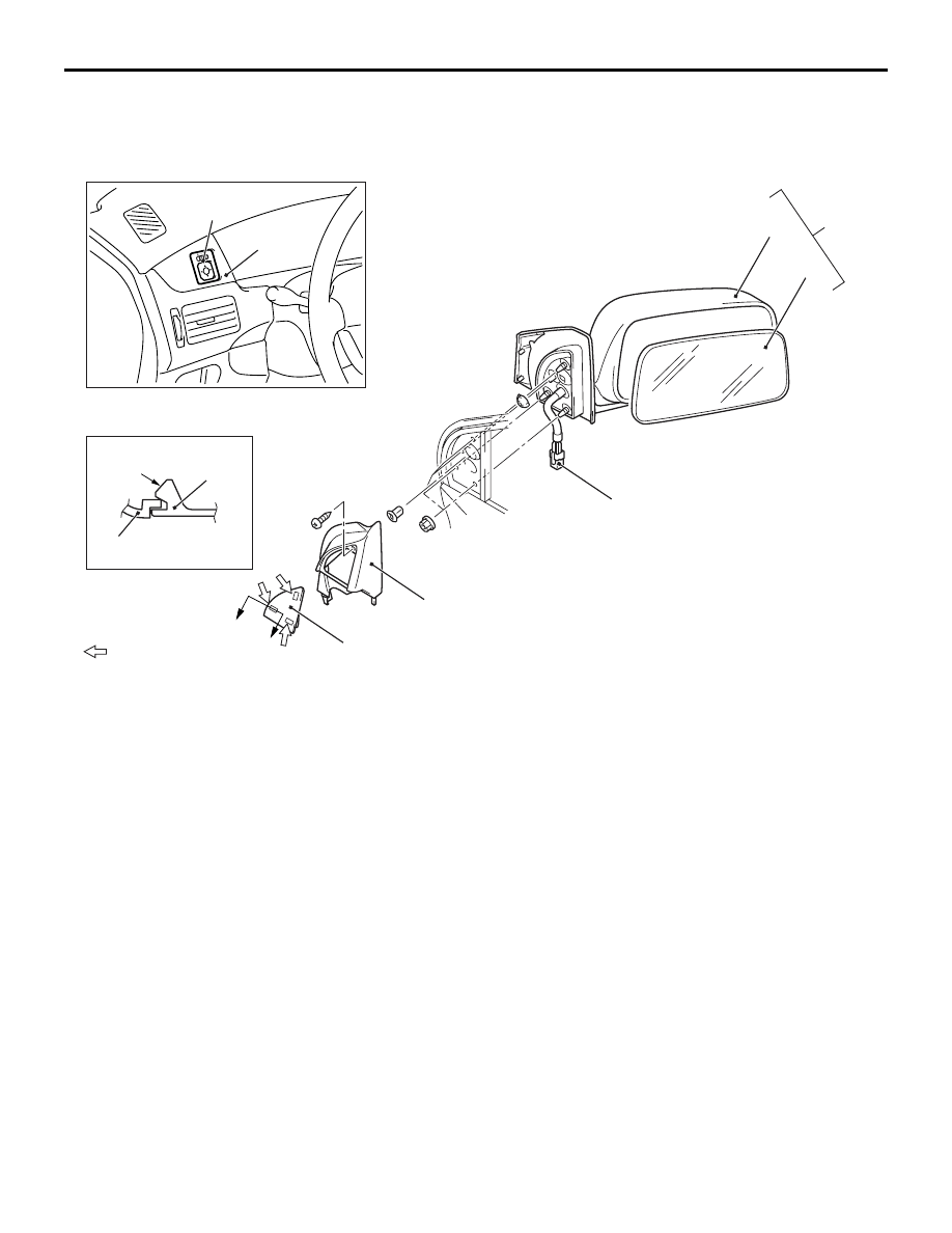
DOOR MIRROR
REMOVAL AND INSTALLATION
M1511006400461
AC304733
Note
: Claw positions
AC
A
A
Section A – A
Claw
1
2
1
2
3
4
5
6
7
8
Door mirror removal steps
1. Cover
2. Delta inner cover
3. Harness connector
4. Door mirror assembly
5. Door mirror body assembly
<<
A
>> >>
A
<< 6. Mirror
Remote controlled mirror switch
removal steps
7. Instrument panel ornament (Refer to
GROUP 52A, Instrument Panel
).
8. Remote controlled mirror switch
DOOR MIRROR
EXTERIOR
51-36
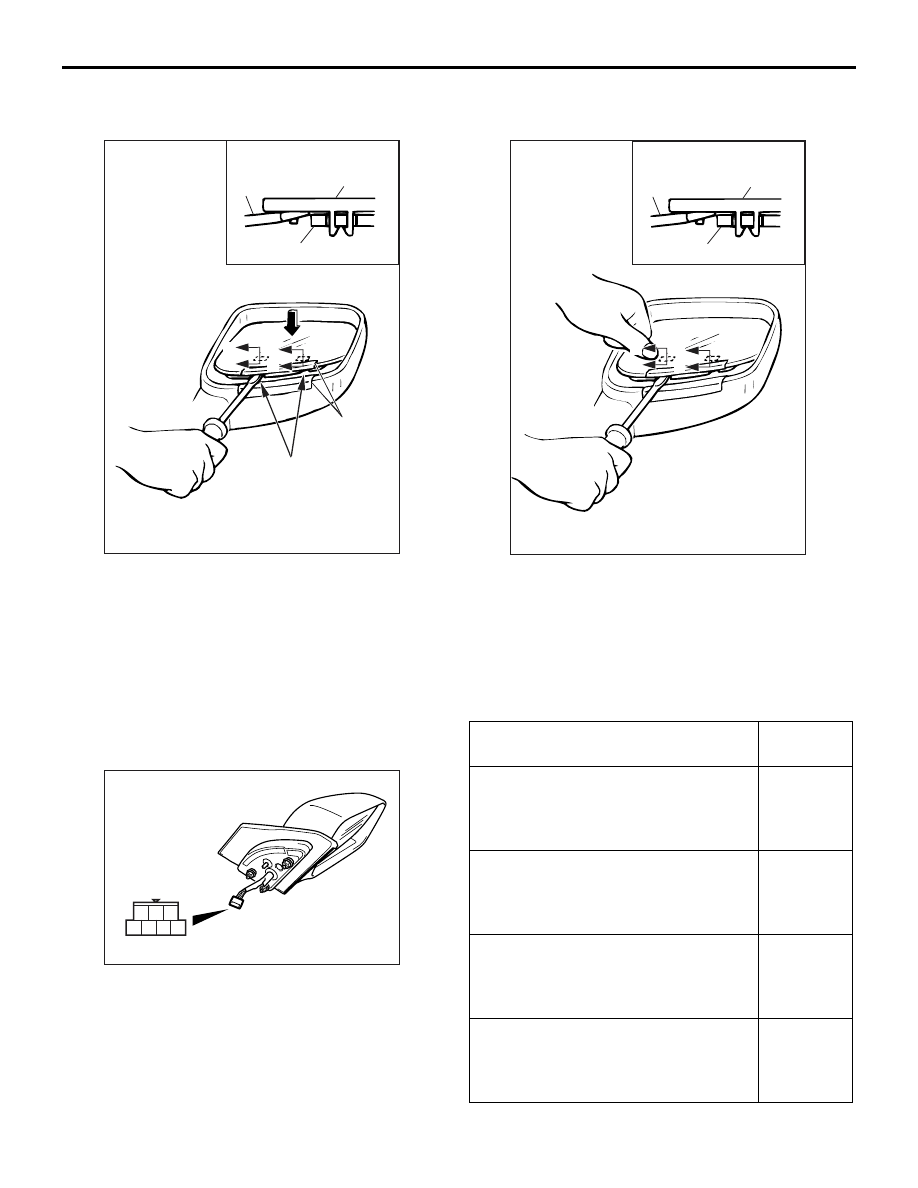
REMOVAL SERVICE POINT
<<A>> MIRROR REMOVAL
AC000441
00007256
Mirror
Flat-tipped
screwdriver
Section A – A
Pivot Plate
Notch
Protective
tape
A
A
A
A
AB
Push the top of the mirror with your hand to tilt it and
attach the protective tape as shown in the illustration.
Then insert a flat-tipped screwdriver in between the
notch at the rear of the mirror and the pivot plate, and
disengage the bottom of the mirror.
INSTALLATION SERVICE POINT
>>A<< MIRROR INSTALLATION
AC000442
00007258
Mirror
Flat-tipped
screwdriver
Section A – A
Pivot plate
A
A
A
A
AB
While supporting the clip position on the underside of
the pivot plate with a flat-tipped screwdriver, press
the clip at the front of the mirror to engage the bottom
of the mirror.
INSPECTION
M1511006500372
ELECTRIC REMOTE CONTROL MIRROR
OPERATION CHECK
AC202548
1
4 5 6 7
2 3
Check that the mirror moves as described in the
table when each terminal is connected to the battery.
Battery connection
Direction
operation
• Connect terminal 5 to the negative
battery terminal.
• Connect terminal 7 to the positive
battery terminal.
Mirror
glass
should face
upward
• Connect terminal 7 to the negative
battery terminal.
• Connect terminal 5 to the positive
battery terminal.
Mirror
glass
should face
downward
• Connect terminal 5 to the negative
battery terminal.
• Connect terminal 6 to the positive
battery terminal.
Mirror
glass
should face
to the right
• Connect terminal 6 to the negative
battery terminal.
• Connect terminal 5 to the positive
battery terminal.
Mirror
glass
should face
to the left
Нет комментариевНе стесняйтесь поделиться с нами вашим ценным мнением.
Текст