Mitsubishi Lancer Evolution IX. Manual — part 526

TROUBLESHOOTING
ANTI-SKID BRAKING SYSTEM (ABS)
35B-135
DATA LIST REFERENCE TABLE
M1352011500702
The following items can be read by the M.U.T.-II/III
from the ABS-ECU input data.
M.U.T.-II/III
display
Item
No.
Check item
Checking requirements
Normal valve
FR SNSR
11
Front-right wheel speed
sensor
Drive the vehicle
Vehicle speeds
displayed on the
speedometer
and M.U.T.-II/III
are identical.
FL SNSR
12
Front-left wheel speed
sensor
RR SNSR
13
Rear-right wheel speed
sensor
RL SNSR
14
Rear-left wheel speed
sensor
BATT.
VOLTAGE
21
ABS-ECU power supply
voltage
Ignition switch: ON
10
− 16 V
PARKING
SW
29
Parking brake switch
Pull the parking brake lever.
ON
Release the parking brake lever.
OFF
GS
(STRAIGHT)
32
Longitudinal G-sensor
When vehicle stops.
2.4
− 2.6 V
When vehicle is driven.
1.0
− 4.0 V
STOP LAMP
SW
36
Stop lamp switch
Depress the brake pedal.
ON
Release the brake pedal.
OFF
ST-N
MEMORY
37
Steering wheel sensor
neutral position learning
After driving straight at vehicle speed
over 10 km/h.
ON
Before driving with ignition switch ON.
OFF
GS
(LATERAL)
71
Lateral G-sensor
When vehicle stops.
2.4
− 2.6 V
When vehicle is driven.
1.0
− 4.0 V
ST-N
74
Steering wheel sensor
(ST-N)
Ignition switch: ON Steering: Neutral
position and fully
turned
ON
Steering: Except
for the above
OFF
ST-1
75
Steering wheel sensor
(ST-1)
Ignition switch: ON Steering: Turn
slowly.
Display ON and
OFF alternately
ST-2
76
Steering wheel sensor
(ST-2)
ST ANGLE
86
Steering degree
• Ignition switch:
ON
• Steering wheel
sensor neutral
position
learning is
finished
(service data
item No.37
displays ON).
Steering: Turn 90
°
to the right.
+ 90
°
Steering: Neutral
OFF
Steering: Turn 90
°
to the left.
- 90
°
TROUBLESHOOTING
ANTI-SKID BRAKING SYSTEM (ABS)
35B-136
ACTUATOR TEST REFERENCE TABLE
M1352011600709
The M.U.T.-II/III activates the following actuators for
testing.
NOTE: If the ABS-ECU runs down, actuator testing
cannot be carried out.
NOTE: Actuator testing is only possible when the
vehicle is stationary.
ACTUATOR TEST SPECIFICATIONS
CHECK AT ABS-ECU
M1352011800695
Use the following steps to remove the connector
cover of the ABS-ECU and then measure the termi-
nal voltage.
1. Move the lock lever of the ABS-ECU connector as
shown in the illustration, and then disconnect the
ABS-ECU as connector.
2. Push up and unlock the hooks of the ABS-ECU
connector as shown in the illustration, then
remove the connector cover.
AC100172 AG
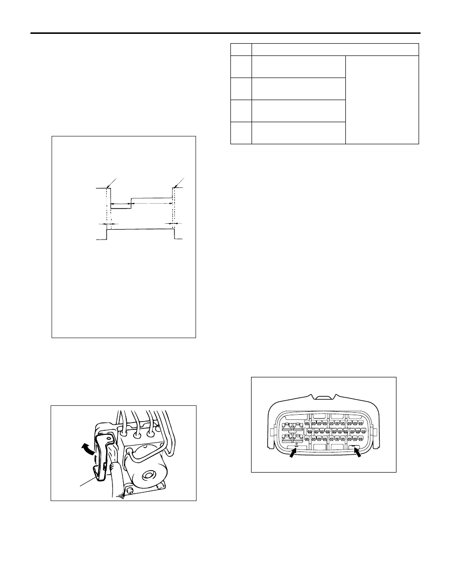
Activation pattern
A
B
C
Solenoid
valve
End of
activation
Start of
activation
1 s
2 s
Pump
motor
ON
OFF
NOTE
A:
B:
C:
Hydraulic pressure increases
Hydraulic pressure holds
Hydraulic pressure decreases
0.01 s
0.05 s
No. Item
01
Solenoid valve for
front-left wheel
Solenoid valves
and pump motors
in the hydraulic
unit (simple
inspection mode)
02
Solenoid valve for
front-right wheel
03
Solenoid valve for
rear-left wheel
04
Solenoid valve for
rear-right wheel
AC211555
AB
Lock lever
AC211694
AB

TROUBLESHOOTING
ANTI-SKID BRAKING SYSTEM (ABS)
35B-137
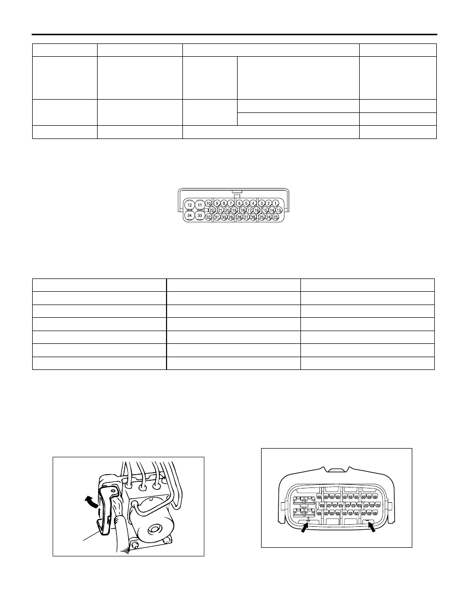
TERMINAL VOLTAGE CHECK CHART
1. Measure the voltages between terminals (12)
(earth terminal) and each respective terminal.
2. The terminal layout is shown in the illustration.
NOTE: Do not measure terminal voltage for approxi-
mately three seconds after the ignition switch is
turned "ON." The ABS-ECU performs the initial
check during that period.
AC211716
Terminal No.
Check item
Checking requirements
Normal condition
1
Parking brake switch Pull the parking brake lever.
1 V or less
Release the parking brake lever.
System voltage
2
M.U.T.-II/III
When the M.U.T.-II/III is connected
Serial
communication
with M.U.T.-II/III
When the M.U.T.-II/III is not connected
1 V or less
4
Steering wheel
sensor (ST-N)
Ignition
switch: "ON"
Steering wheel: Neutral
position and fully turned.
0.8
− 2.1 V
Steering wheel: Except for the
above
2.7
− 4.4 V
5
Diagnosis
changeover input
When the M.U.T.-II/III is connected
Approximately 0 V
When the M.U.T.-II/III is not connected
System voltage
10
ABS-ECU power
supply
Ignition switch: "ON"
System voltage
Ignition switch: "START" or "ACC"
Approximately 0 V
11
Solenoid valve power
supply
Always
System voltage
14
Lateral G-sensor
input
Ignition switch: "ON"
2.4
− 2.6 V
(horizontal
position)
15
Longitudinal
G-sensor earth
Always
0 V
17
Steering wheel
sensor (ST-2)
Ignition
switch: "ON"
Steering wheel: Turned
Variation in the
voltage value 0.8
−
2.1 V and 2.7
− 4.4
V
19
Stop lamp monitor
input
Ignition
switch: "ON"
Stop lamp switch: "ON"
System voltage
Stop lamp switch: "OFF"
1 V or less
24
Lateral G-sensor
earth
Always
0 V
25
Longitudinal
G-sensor input
Ignition switch: "ON"
2.4
− 2.6 V
(horizontal
position)
ON-VEHICLE SERVICE
ANTI-SKID BRAKING SYSTEM (ABS)
35B-138
RESISTANCE AND CONTINUITY BETWEEN HARNESS-SIDE CONNECTOR
TERMINALS
1. Turn the ignition switch to the "LOCK" (OFF)
position and disconnect the ABS-ECU connectors
before checking resistance and continuity.
2. Check the resistance and continuity between the
terminals indicated in the table below.
3. The terminal layout is shown in the illustration.
ON-VEHICLE SERVICE
WHEEL SPEED SENSOR OUTPUT
VOLTAGE MEASUREMENT
M1352001600612
Lift up the vehicle and release the parking brake.
1. Move the lock lever of the ABS-ECU connector as
shown, and then disconnect the ABS-ECU
connector.
2. Push up and unlock the hooks of the ABS-ECU
connector as shown in the illustration, then
remove the connector cover.
26
Steering wheel
sensor (ST-1)
Ignition
switch: "ON"
Steering wheel: Turned
Variation in the
voltage value 0.8
−
2.1 V and 2.7
− 4.4
V
27
ABS-ECU warning
lamp transistor output
Ignition
switch: "ON"
When the lamp off
1 V or less
When the lamp is illuminated
7 V or more
33
Motor power supply
Always
System voltage
Terminal No.
Check item
Checking requirements
Normal condition
AC211717
ABS-ECU terminal No.
Signal
Normal condition
6
− 7
Rear-left wheel speed sensor
1.24
− 1.64 kΩ
8
− 9
Rear-right wheel speed sensor
1.24
− 1.64 kΩ
22
− 31
Front-left wheel speed sensor
1.24
− 1.64 kΩ
29
− 30
Front-right wheel speed sensor
1.24
− 1.64 kΩ
12
− body earth
Earth
Less than 2 ohms
34
− body earth
Earth
Less than 2 ohms
AC211555
AB
Lock lever
AC211694
AB
Нет комментариевНе стесняйтесь поделиться с нами вашим ценным мнением.
Текст