Mitsubishi Lancer Evolution IX. Manual — part 235

SYMPTOM PROCEDURES
SMART WIRING SYSTEM (SWS) USING SWS MONITOR
54C-199
INSPECTION PROCEDURE H-8: The headlamp(s) do not illuminate. <including high-beam indicator>
CAUTION
Whenever the ECU is replaced, ensure that the
input and output signal circuits are normal.
COMMENTS ON TROUBLE SYMPTOM
If any of the headlamps or the high-beam indicator
does not illuminate, the wiring harness connector(s),
the bulb or the fuse may be defective or burned out.
POSSIBLE CAUSES
• Malfunction of the headlamp bulbs
• Malfunction of the high-beam indicator bulb
• Damaged harness wires and connectors
Wire colour code
B : Black LG : Light green G : Green L : Blue W : White Y : Yellow SB : Sky blue
BR : Brown O : Orange GR : Gray R : Red P : Pink V : Violet
HEADLAMP
(HI: RH)
HEADLAMP
(HI: LH)
HEADLAMP
ASSEMBLY
(LH) (LO)
HEADLAMP
ASSEMBLY
(RH) (LO)
COMBINATION
METER
RELAY
BOX
FRONT-ECU
HEADLAMP
RELAY: HI
HEADLAMP
RELAY: LO
Headlamps Circuit
SYMPTOM PROCEDURES
SMART WIRING SYSTEM (SWS) USING SWS MONITOR
54C-200
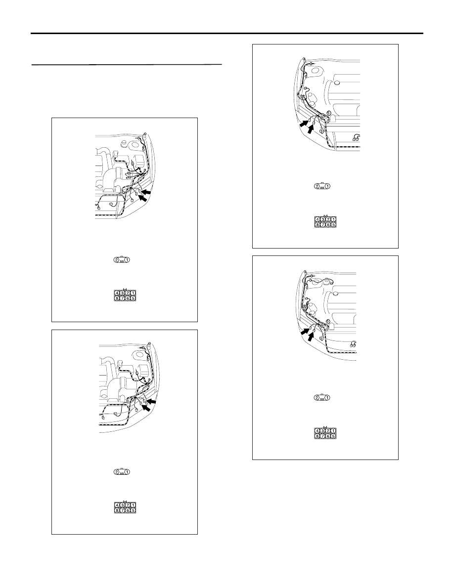
DIAGNOSTIC PROCEDURE
Step 1. Connector check: A-31 <headlamp (LO)
RH>, A-39 <headlamp (LO) LH>, A-21 <headlamp
(HI) RH>, A-15 <headlamp (HI) LH> headlamp
assembly connector or C-01 <high-beam
indicator> combination meter connector
AC310543
Connectors: A-15, A-31
AC
<LHD>
A-15
Harness side
A-31
Harness side
A-15
A-31
AC310476
Connectors: A-15, A-31
AC
<RHD>
A-15
Harness side
A-31
Harness side
A-15
A-31
AC310432
Connectors: A-21, A-39
AC
<LHD>
A-21
Harness side
A-39
Harness side
A-21
A-39
AC310434
Connectors: A-21, A-39
AC
<RHD>
A-21
Harness side
A-39
Harness side
A-21
A-39
SYMPTOM PROCEDURES
SMART WIRING SYSTEM (SWS) USING SWS MONITOR
54C-201
Q: Is the check result normal?
YES :
Go to Step 2.
NO :
Repair the defective connector.
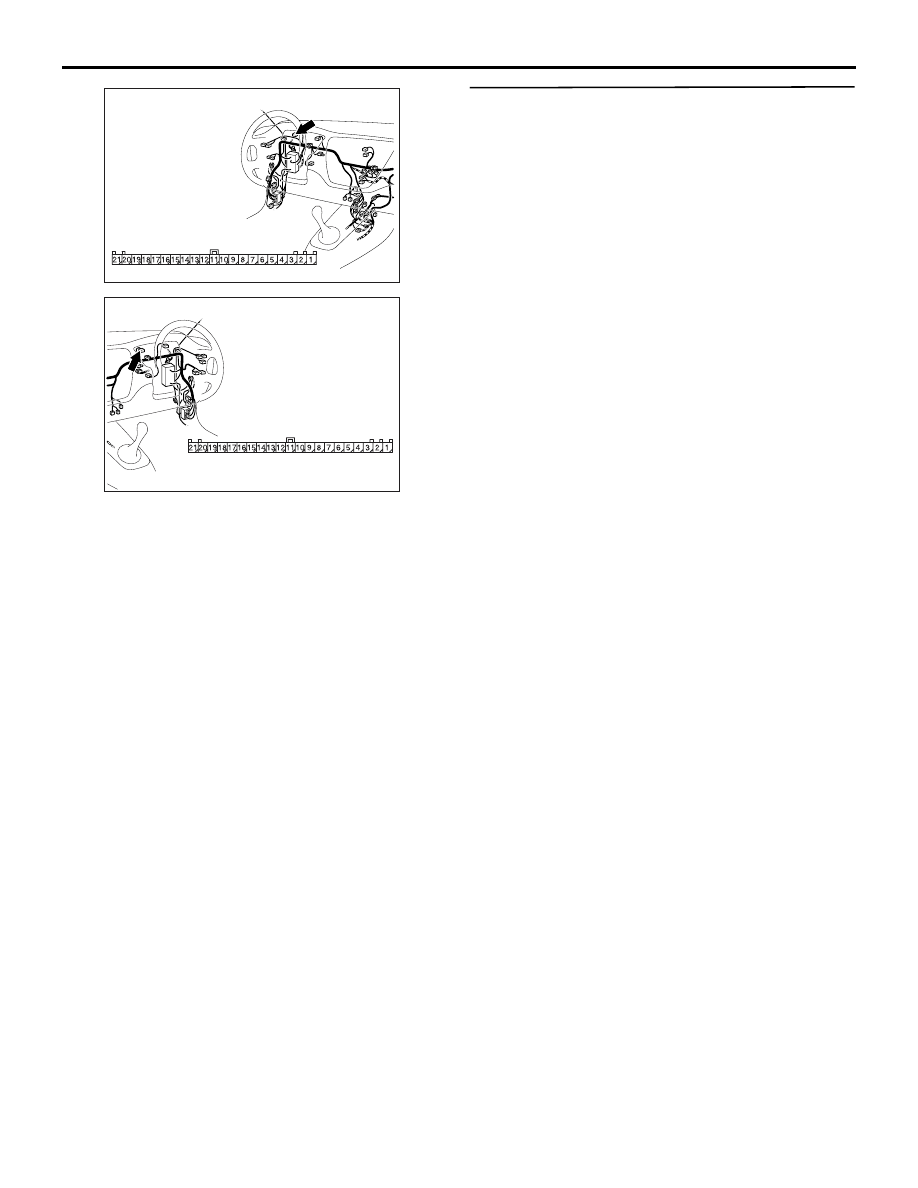
Step 2. Check the bulb(s) of the headlamps or the
high-beam indicator lamp.
Check the bulb(s) of the defective lamp.
Q: Is the check result normal?
YES :
Go to Step 3.
NO :
Replace the bulb(s) of the defective lamp.
AC310446
Connector: C-01
<LHD>
AM
Harness side
AC310456
Connector: C-01
<RHD>
AL
Harness side

SYMPTOM PROCEDURES
SMART WIRING SYSTEM (SWS) USING SWS MONITOR
54C-202
Step 3. Resistance measurement at A-31
<headlamp (LO) RH>, A-39 <headlamp (LO) LH>,
A-21 <headlamp (HI) RH>, A-15 <headlamp (HI)
LH> headlamp assembly connector or C-01
<high-beam indicator> combination meter
connector
AC310543
Connectors: A-15, A-31
AC
<LHD>
A-15
Harness side
A-31
Harness side
A-15
A-31
AC310476
Connectors: A-15, A-31
AC
<RHD>
A-15
Harness side
A-31
Harness side
A-15
A-31
AC310432
Connectors: A-21, A-39
AC
<LHD>
A-21
Harness side
A-39
Harness side
A-21
A-39
AC310434
Connectors: A-21, A-39
AC
<RHD>
A-21
Harness side
A-39
Harness side
A-21
A-39
Нет комментариевНе стесняйтесь поделиться с нами вашим ценным мнением.
Текст