Mitsubishi Lancer Evolution IX. Manual — part 142
SYMPTOM PROCEDURES
SMART WIRING SYSTEM (SWS) NOT USING SWS MONITOR
54B-131
COMMENTS ON TROUBLE SYMPTOM
The windshield wiper motor, the column switch or the
front-ECU may be defective.
POSSIBLE CAUSES
• Malfunction of the windshield wiper motor
• Malfunction of the column switch
• Malfunction of the front-ECU
• Damaged harness wires and connectors
DIAGNOSTIC PROCEDURE
Step 1. M.U.T.-II/III diagnosis code.
When the ignition switch is turned to the LOCK
(OFF) position, check that the ETACS-ECU does not
set the diagnosis code.
Q: Is the diagnosis code set?
YES :
Refer to diagnosis code chart
NO :
Go to Step 2.
Step 2. Pulse check
Check the input signals below which are related to
the windshield wiper.
OK: The M.U.T.-II/III sounds or the voltmeter
needle fluctuates.
Q: Is the check result normal?
All the signals are received normally :
Go to Step
3.
The ignition switch (ACC) signal is not received. :
Refer to inspection procedure L-1 "The
ignition switch (ACC) signal is not received
."
Windshield mist wiper switch signal is not
received. :
Refer to inspection procedure L-5 "The
column switch (windshield wiper washer
and rear wiper washer switch) signal is not
received
."
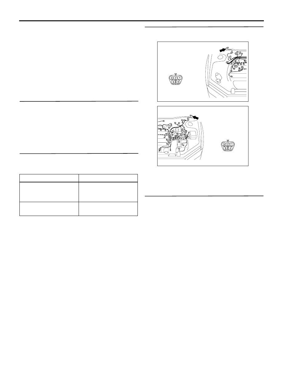
Step 3. Connector check: B-01 windshield wiper
motor connector
Q: Is the check result normal?
YES :
Go to Step 4.
NO :
Repair the connector.
Step 4. Check the windshield wiper motor
assembly.
Refer to GROUP 51
− Windshield wiper
.
Q: Is the check result normal?
YES :
Go to Step 5
NO :
Replace the windshield wiper motor
assembly.
System switch
Check condition
Ignition switch (ACC)
When turned from the
LOCK (OFF) position to
the ACC position.
Windshield mist wiper
switch
When the switch is
turned from off to on.
AC310437
Connector: B-01 <LHD>
AB
Harness side
B-01 (GR)
AC310477
Connector: B-01 <RHD>
AD
Harness side
B-01 (GR)

SYMPTOM PROCEDURES
SMART WIRING SYSTEM (SWS) NOT USING SWS MONITOR
54B-132
Step 5. Resistance measurement at the B-01
windshield wiper motor connector
(1) Disconnect the connector, and measure at the
wiring harness side.
(2) Continuity between B-01 windshield wiper motor
connector terminal No.5 and body earth
OK: 2
Ω or less
Q: Is the check result normal?
YES :
Go to Step 7.
NO :
Go to Step 6.
Step 6. Check the wiring harness between B-01
windshield wiper motor connector terminal No.5
and body earth.
• Check the earth wires for open circuit.
Q: Is the check result normal?
YES :
The trouble can be an intermittent
malfunction (Refer to GROUP 00
− How to
Cope with Intermittent Malfunction
NO :
Repair the wiring harness.
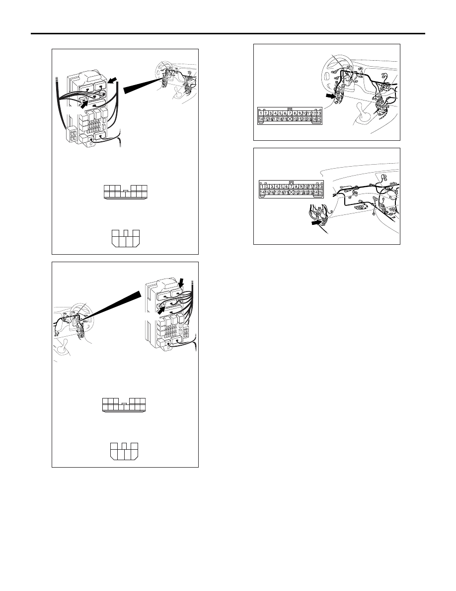
Step 7. Connector check: A-11X front-ECU
connector
Q: Is the check result normal?
YES :
Go to Step 8.
NO :
Repair the connector.
AC310437
Connector: B-01 <LHD>
AB
Harness side
B-01 (GR)
AC310477
Connector: B-01 <RHD>
AD
Harness side
B-01 (GR)
4
1
2
5
3
AC301635
Connector B-01
(Harness side)
AC
AC310437
Connector: B-01 <LHD>
AB
Harness side
B-01 (GR)
AC310477
Connector: B-01 <RHD>
AD
Harness side
B-01 (GR)
AC310572AC
Connector: A-11X
Relay box side
Battery
29
31 30
28 27
25
26
24
21
22
23

SYMPTOM PROCEDURES
SMART WIRING SYSTEM (SWS) NOT USING SWS MONITOR
54B-133
Step 8. Voltage measurement at the A-11X
front-ECU connector
(1) Remove the front-ECU, and measure at the relay
box side.
(2) Ignition switch: ACC
(3) Check the voltage between the A-11X front-ECU
connector terminal No.24 and body earth.
OK: System voltage
Q: Is the check result normal?
YES :
Go to Step 10.
NO :
Go to Step 9.
Step 9. Check the wiring harness between A-11X
front-ECU connector terminal No.24 and the
ignition switch (ACC).
AC310572AC
Connector: A-11X
Relay box side
Battery
29
31 30
28 27
25
26
24
21
22
23
24
29
30
31
2827
25
26
21
2322
AC304768
Connector A-11X
(Relay box side)
AB
AC310572AC
Connector: A-11X
Relay box side
Battery
29
31 30
28 27
25
26
24
21
22
23
SYMPTOM PROCEDURES
SMART WIRING SYSTEM (SWS) NOT USING SWS MONITOR
54B-134
NOTE:
Prior to the wiring harness inspection, check the
junction block connectors C-210, C-211 and interme-
diate connector C-129 and repair if necessary.
• Check the power supply line to the ignition switch
(ACC) for open circuit.
Q: Is the check result normal?
YES :
The trouble can be an intermittent
malfunction (Refer to GROUP 00
− How to
Cope with Intermittent Malfunction
NO :
Repair the wiring harness.
AC310449
Connectors: C-210, C-211 <LHD>
AF
C-210
C-211
Junction block (front view)
C-210
Harness side
10
1
6
14
5
12
13
4
11
7
2
3
8
9
C-211
Harness side
4
6 5
3
2
1
AC310459
Connectors: C-210, C-211 <RHD>
AF
C-210
C-211
Junction block (front view)
C-210
Harness side
10
1
6
14
5
12
13
4
11
7
2
3
8
9
C-211
Harness side
4
6 5
3
2
1
AC310446
Connector: C-129
<LHD>
AI
AC310454
Connector: C-129
<RHD>
AJ
Нет комментариевНе стесняйтесь поделиться с нами вашим ценным мнением.
Текст