Mitsubishi Lancer Evolution IX. Manual — part 263
INPUT SIGNAL PROCEDURES
SMART WIRING SYSTEM (SWS) USING SWS MONITOR
54C-311
NOTE:
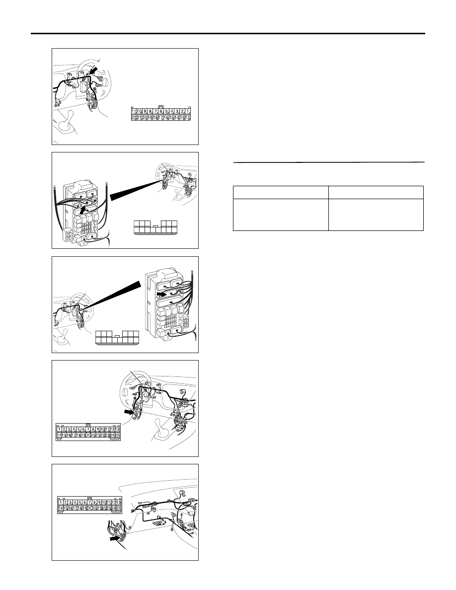
Prior to the wiring harness inspection, check joint
connector C-23 <RH drive vehicles>, junction block
connector C-210 or intermediate connector C-129,
and repair if necessary.
• Check the power supply line to the ignition switch
(ACC) for open circuit.
Q: Is the check result normal?
YES :
The trouble can be an intermittent
malfunction (Refer to GROUP 00
− How to
Cope with Intermittent Malfunction
NO :
Repair the wiring harness.
Step 7. Pulse check
Check the input of the interior lamp loaded signal.
OK: The M.U.T.-II/III sounds or the voltmeter
needle fluctuates.
Q: Is the check result normal?
YES :
The trouble can be an intermittent
malfunction (Refer to GROUP 00
− How to
Cope with Intermittent Malfunction
NO :
Replace the ETACS-ECU.
AC310456
Connector: C-23
AJ
<RHD>
C-23 (B)
Harness side
AC310448
Junction block (front view)
Connector: C-210
AK
<LHD>
Harness side
10
1
6
14
5
12
13
4
11
7
2
3
8
9
AC310458
Junction block (front view)
Connector: C-210
AH
<RHD>
Harness side
10
1
6
14
5
12
13
4
11
7
2
3
8
9
AC310446
Connector: C-129
<LHD>
AI
AC310454
Connector: C-129
<RHD>
AJ
System switch
Check condition
Interior lamp loaded
signal
When a load is applied
through multi-purpose
fuse No.18

INPUT SIGNAL PROCEDURES
SMART WIRING SYSTEM (SWS) USING SWS MONITOR
54C-312
INSPECTION PROCEDURE L-16: The door lock key cylinder switch signal is not detected.
CAUTION
Whenever the ECU is replaced, ensure that the
input signal circuit is normal.
COMMENTS ON TROUBLE SYMPTOM
Input signal from the door lock key cylinder switch is
used to operate the central door locking function. If
the signal is abnormal, the central door locking func-
tion will not work normally.
POSSIBLE CAUSES
• Malfunction of the door lock key cylinder switch
• Malfunction of the ETACS-ECU
• Damaged harness wires and connectors
Door Lock Key Cylinder Switch Input Circuit
Wire colour code
B : Black LG : Light green G : Green L : Blue W : White Y : Yellow SB : Sky blue
BR : Brown O : Orange GR : Grey R : Red P : Pink V : Violet PU : Purple
DOOR LOCK
KEY CYLINDER
SWITCH
ETACS-ECU
INPUT SIGNAL PROCEDURES
SMART WIRING SYSTEM (SWS) USING SWS MONITOR
54C-313
DIAGNOSIS PROCEDURE
Step 1. Connector check: E-12 door lock key
cylinder switch connector
Q: Is the check result normal?
YES :
Go to Step 2.
NO :
Repair the defective connector.
Step 2. Check the door lock key cylinder switch.
Refer to GROUP 42
− Door
Q: Is the check result normal?
YES :
Go to Step 3.
NO :
Replace the door lock key cylinder switch.
Step 3. Resistance measurement at the E-12 door
lock key cylinder switch connector
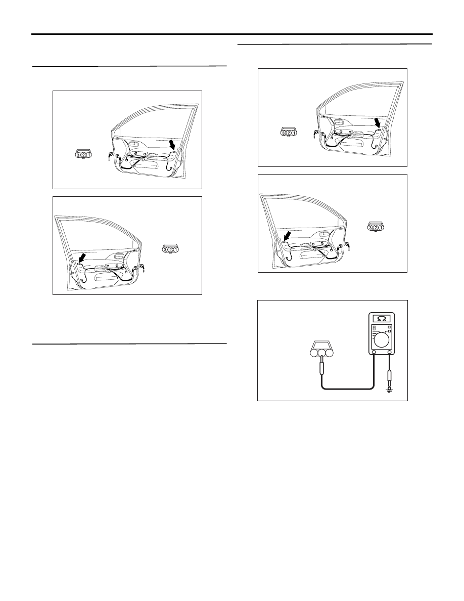
(1) Disconnect the connector, and measure at the
wiring harness side.
(2) Resistance between E-12 door lock key cylinder
switch connector terminal No.2 and body earth
OK: 2
Ω or less
Q: Is the check result normal?
YES :
Go to Step 5.
NO :
Go to Step 4.
AC310488
Harness side
AC
Connector: E-12
<LHD>
E-12(B)
Front door (RH)
AC310498
Harness side
AB
Connector: E-12
<RHD>
E-12(B)
AC310488
Harness side
AC
Connector: E-12
<LHD>
E-12(B)
Front door (RH)
AC310498
Harness side
AB
Connector: E-12
<RHD>
E-12(B)
AC301541DM
Connector E-12
(Harness side)
3
1
2
INPUT SIGNAL PROCEDURES
SMART WIRING SYSTEM (SWS) USING SWS MONITOR
54C-314
Step 4. Check the wiring harness between E-12
door lock key cylinder switch connector terminal
No.2 and body earth.
NOTE:
Prior to the wiring harness inspection, check interme-
diate connector C-110 <LH drive vehicles> or C-17
<RH drive vehicles>, and repair if necessary.
• Check the earth wires for open circuit.
Q: Is the check result normal?
YES :
Intermittent malfunction. (Refer to GROUP
00
− How to Cope with Intermittent
).
NO :
Repair the wiring harness.
Step 5. Connector check: C-227 ETACS-ECU
connector
Q: Is the check result normal?
YES :
Go to Step 6.
NO :
Repair the defective connector.
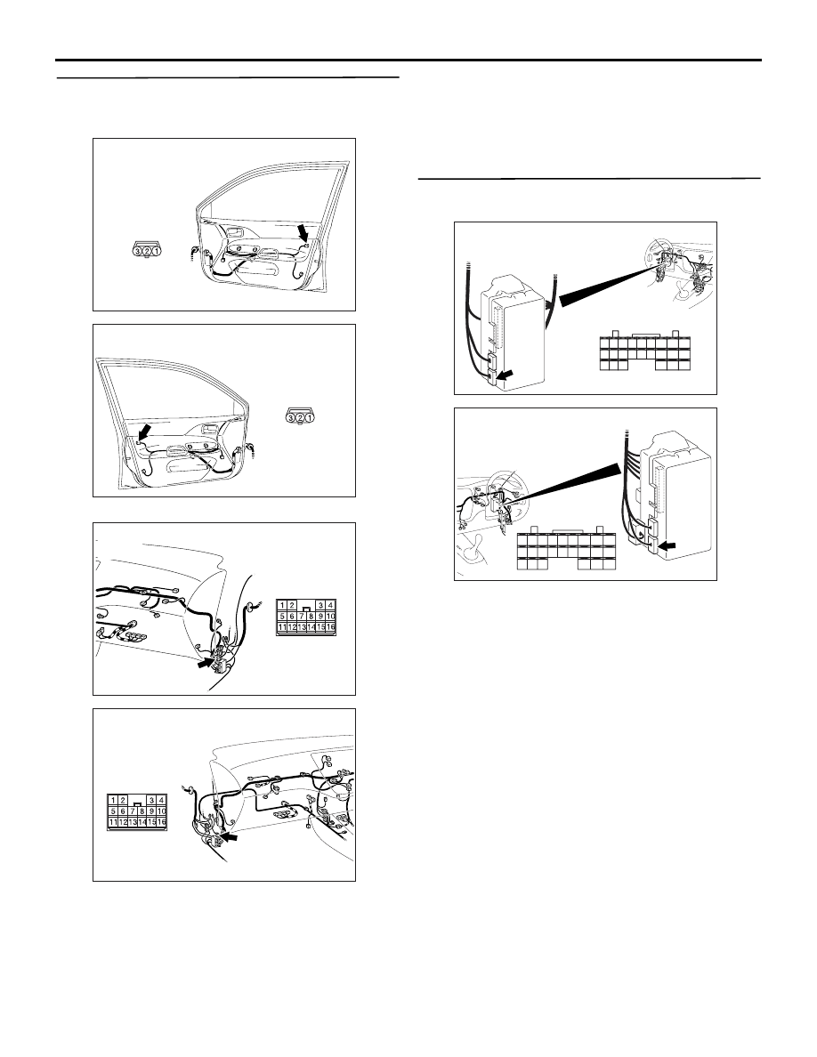
AC310488
Harness side
AC
Connector: E-12
<LHD>
E-12(B)
Front door (RH)
AC310498
Harness side
AB
Connector: E-12
<RHD>
E-12(B)
AC310452
Connector: C-110
AG
<LHD>
AC310454
Connector: C-17
AK
<RHD>
AC310450
Connector: C-227
AG
Junction block
(rear view)
Harness side
<LHD>
28
37
43
29
44
38
23
32
41
24
25
26
27
34
42
36 35
33
21
22
30
39
40
31
AC310461
Harness side
Junction block (rear view)
Connector: C-227
AF
<RHD>
21
22
23
24
25
26
27
28
29
30
31
32
33
34
35
36
37
38
39
40
41
42
43
44
Нет комментариевНе стесняйтесь поделиться с нами вашим ценным мнением.
Текст