Mitsubishi Lancer Evolution IX. Manual — part 309

TROUBLESHOOTING
REAR AXLE
27-11
DIAGNOSTIC TROUBLE CODE
PROCEDURES
Code No.71: Proportioning valve <AYC> system
4WD-ECU
PROPORTIONING
VALVE
DIRECTION
VALVE (LH)
DIRECTION
VALVE (RH)
FOR AYC
CONTROL
Wire colour code
B : Black LG : Light green G : Green L : Blue W : White Y : Yellow SB : Sky blue
BR : Brown O : Orange GR : Gray R : Red P : Pink V : Violet
Proportioning valve system/direction valve system circuit
18
3
16
15
14
1 2
17
4 5
8
20
19
6 7
2122
9 10
25
13
24
23
12
11
2
1
3
13
12
14
21
10
5
4
6
16
15
17
7 8 9
19
18
20
11
22
OPERATION
• After processing information of various sensors
and switches, the 4WD-ECU calculates the
amount of AYC torque movement and direction,
and controls the proportioning valve.
• The current flows from the 4WD-ECU to activate
the proportioning valve, which controls oil pres-
sure supplied to the AYC clutches.
DIAGNOSIS CODE SET CONDITIONS
Diagnosis code No.71 is set when the proportioning
valve control circuit is open circuited or
short-circuited.
PROBABLE CAUSES
• Malfunction of the proportioning valve
• Damaged harness wires and connectors
• Malfunction of the 4WD-ECU
TROUBLESHOOTING
REAR AXLE
27-12
DIAGNOSIS
STEP 1. M.U.T.-II/III data list
Set M.U.T.-II/III to data reading mode, and check the
data list item.
Item 12: Proportioning valve current <AYC> (Refer to
Data List Table
Q: Is the check result normal?
YES :
This malfunction is intermittent. Refer to
GROUP 00, How to Use
Troubleshooting/Inspection Service Points
−
How to Cope with Intermittent Malfunction
.
NO :
Go to Step 2.
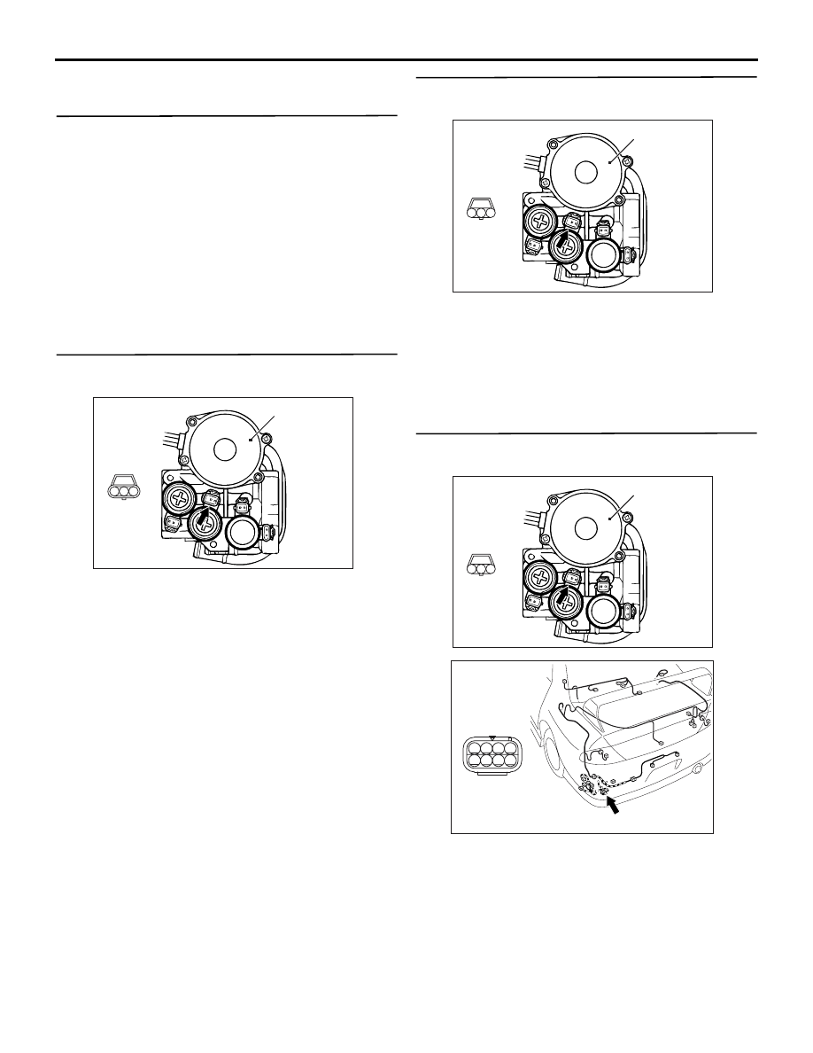
STEP 2. Measure the resistance at proportioning
valve connector F-25.
AC310716
1
3
2
Connector: F-25
F-25 (3-B)
AB
Hydraulic unit
assembly
Disconnect the connector, and measure the resist-
ance between terminal 2 and 3 at the proportioning
valve side.
OK: 4.7
Ω or less
Q: Is the check result normal?
YES :
Go to Step 3.
NO :
Replace the hydraulic unit.
STEP 3. Measure the resistance at
proportioning valve connector F-25.
AC310718
3
1
2
Connector: F-25
F-25 (3-B)
AB
Hydraulic unit
assembly
Harness
side
Measure the resistance between terminal 2 and
earth at the wiring harness side.
OK: 2
Ω or less
Q: Is the check result normal?
YES :
Go to Step 4.
NO :
Repair the defective connector.
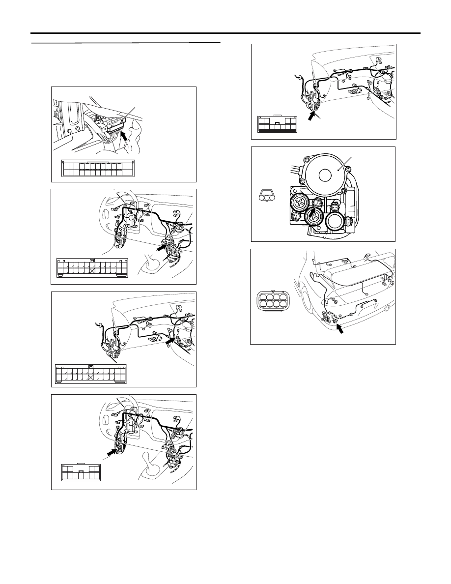
STEP 4. Connectors check: F-25 proportioning
valve connector, F-21 intermediate connector
AC310718
3
1
2
Connector: F-25
F-25 (3-B)
AB
Hydraulic unit
assembly
Harness
side
7
3
5
1
6
2
8
4
AC310719AB
Connector: F21
F-21 (8-B)
Check for the contact with terminals.
Q: Is the check result normal?
YES :
Go to Step 5.
NO :
Repair the defective connector.

TROUBLESHOOTING
REAR AXLE
27-13
STEP 5. Check the harness wires between
proportioning valve connector F-25 terminal 2
and intermediate connector F-21 terminal 4 and
earth.
AC310718
3
1
2
Connector: F-25
F-25 (3-B)
AB
Hydraulic unit
assembly
Harness
side
7
3
5
1
6
2
8
4
AC310719AB
Connector: F21
F-21 (8-B)
Check the earth line for open circuit.
Q: Is the check result normal?
YES :
Go to Step 6.
NO :
Repair the wiring harness.
TROUBLESHOOTING
REAR AXLE
27-14
STEP 6. Connectors check: C-25 4WD-ECU
connector, C-124, C-134 and F-21 intermediate
connectors, and F-25 proportioning valve
connector
AC310721
18
16
1415
17
23
21
1920
22
26
2425
3
1 2
4 5
10
8
6 7
9
13
12
11
4WD-ECU
C-25 (26-Y)
Connector: C-25
AB
AC310722
18
3
16
15
14
1 2
17
4 5
8
20
19
6 7
2122
9 10
25
13
24
23
12
11
Connector: C-124
<LHD>
AB
C-124 (25)
AC310738
18
3
16
15
14
1 2
17
4 5
8
20
19
6 7
2122
9 10
25
13
24
23
12
11
Connector: C-124
<RHD>
AB
C-124 (25)
AC310723
6
2
5
1
7 8
11
4
9 10
3
Connector: C-134
<LHD>
AB
C-134 (11-B)
AC310726
6
2
5
1
7 8
11
4
9 10
3
Connector: C-134
<RHD>
AB
C-134 (11-B)
AC310718
3
1
2
Connector: F-25
F-25 (3-B)
AB
Hydraulic unit
assembly
Harness
side
7
3
5
1
6
2
8
4
AC310719AB
Connector: F21
F-21 (8-B)
Check for the contact with terminals.
Q: Is the check result normal?
YES :
Go to Step 7.
NO :
Repair the defective connector.
Нет комментариевНе стесняйтесь поделиться с нами вашим ценным мнением.
Текст