Mitsubishi Lancer Evolution IX. Manual — part 591

TROUBLESHOOTING <ACD>
MANUAL TRANSMISSION (FF)
22A-47
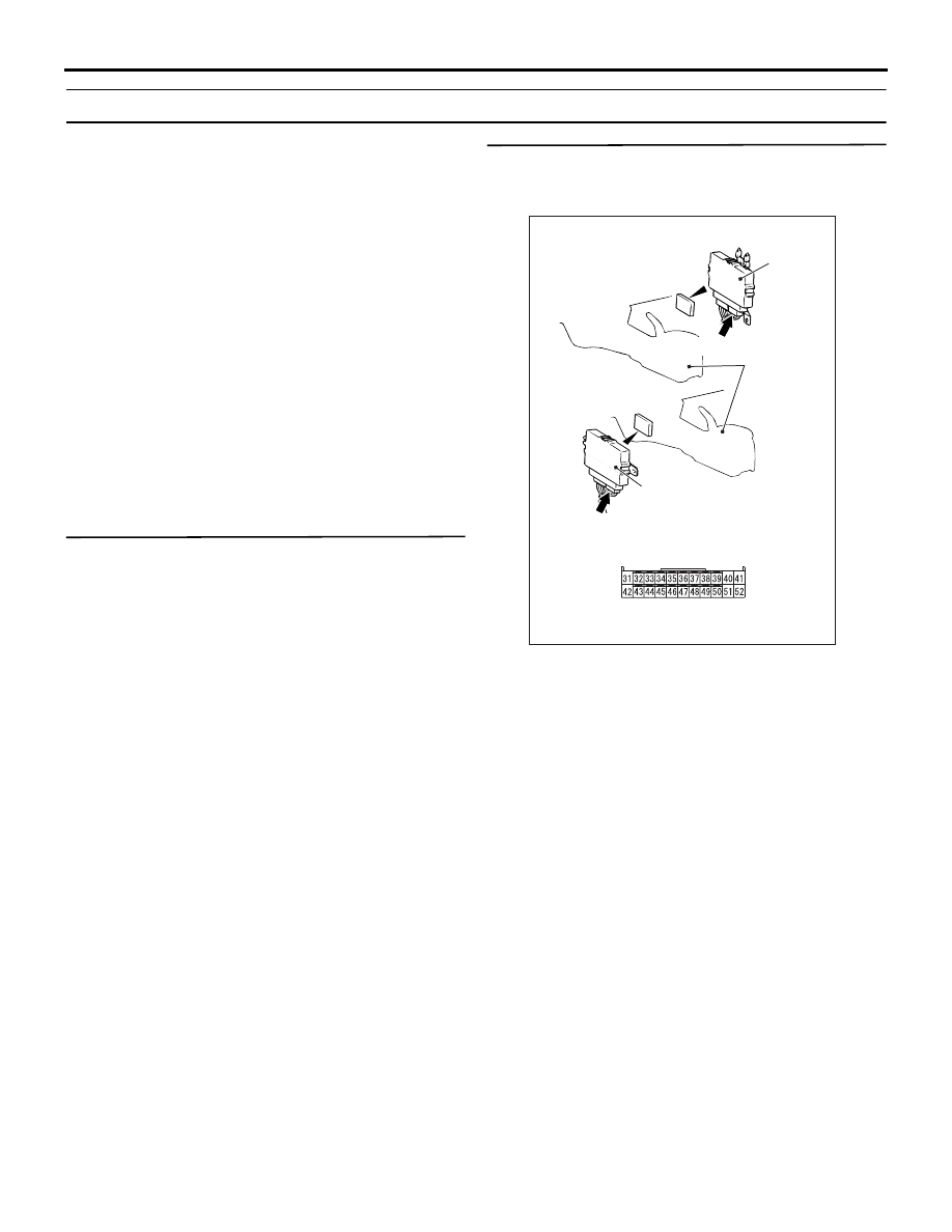
STEP 3. Connectors check: C-25 4WD-ECU
connector, C-122, C-134, F-21 intermediate
connector, F-26 pressure sensor connector <LH
drive vehicles> or C-25 4WD-ECU connector,
C-134, C-138, F-21 intermediate connector, F-26
pressure sensor connector <RH drive vehicles>.
Check for the contact with terminals.
Q: Is the check result normal?
YES :
Go to Step 4.
NO :
Repair the defective connector.
AC311002
4WD-ECU
Harness side
C-25 (Y)
AB
Connector: C-25
4WD-ECU
C-25 (Y)
Rear console
assembly
<LH drive vehicles>
<RH drive vehicles>
AC311015AC
Connector: C-122 <LH drive vehicles>
C-122
AC311015AG
Connector: C-134 <LH drive vehicles>
C-134 (B)
AC311016AD
Connector: C-134 <RH drive vehicles>
C-134 (GR)
AC311016AB
Connector: C-138 <RH drive vehicles>
C-138
AC311042
F-21 (B)
AB
Connector: F-21, F-26
F-26 (B)
Sensor side
F-21
F-26

TROUBLESHOOTING <ACD>
MANUAL TRANSMISSION (FF)
22A-48
STEP 4. Check the harness between 4WD-ECU
connector C-25 terminal No.10 and pressure
sensor connector F-26 terminal No.3.
Check the power supply line, output line, earth line
for short or open circuit.
Q: Is the check result normal?
YES :
Replace the 4WD-ECU.
NO :
Repair the wiring harness.
AC311002
4WD-ECU
Harness side
C-25 (Y)
AB
Connector: C-25
4WD-ECU
C-25 (Y)
Rear console
assembly
<LH drive vehicles>
<RH drive vehicles>
AC311042
AC
Connector: F-26
F-26 (B)
Sensor side
F-26
TROUBLESHOOTING <ACD>
MANUAL TRANSMISSION (FF)
22A-49
Code No.47 Pressure sensor system (abnormal power supply)
PRESSURE SENSOR SYSTEM CIRCUIT
Refer to
OPERATION
Refer to
DIAGNOSIS CODE SET CONDITIONS
Code No.47 is set when the pressure sensor power
supply voltage is above 4.0V during pressure sensor
power OFF or less than 4.0V during pressure sensor
power ON.
PROBABLE CAUSES
• Malfunction of the pressure sensor
• Damaged harness wires and connectors
• Malfunction of the 4WD-ECU
DIAGNOSIS
STEP 1. M.U.T.-II/III data list
Item 19: Pressure sensor power supply (Refer to
data list reference table
).
Q: Is the check result normal?
YES :
Intermittent malfunction (Refer to GROUP
00
− How to Cope with Intermittent
NO :
Go to Step 2.
STEP 2. Measure the voltage at 4WD-ECU
connector C-26.
(1) Turn the ignition switch to the ON position.
(2) Measure the voltage between 4WD-ECU
connector C-26 terminal No.43 and earth.
OK: 5 V
Q: Is the check result normal?
YES :
Go to Step 3.
NO :
Go to Step 5.
AC311002
4WD-ECU
Harness side
C-26 (Y)
AC
Connector: C-26
4WD-ECU
C-26 (Y)
Rear console
assembly
<LH drive vehicles>
<RH drive vehicles>

TROUBLESHOOTING <ACD>
MANUAL TRANSMISSION (FF)
22A-50
STEP 3. Connector check: C-26 4WD-ECU
connector.
Check for the contact with terminals.
Q: Is the check result normal?
YES :
Go to Step 4.
NO :
Repair the defective connector.
STEP 4. M.U.T.-II/III data list
Item 19: Pressure sensor power supply (Refer to
data list reference table
).
Q: Is the check result normal?
YES :
Intermittent malfunction (Refer to GROUP
00
− How to Cope with Intermittent
).
NO :
Replace the 4WD-ECU.
AC311002
4WD-ECU
Harness side
C-26 (Y)
AC
Connector: C-26
4WD-ECU
C-26 (Y)
Rear console
assembly
<LH drive vehicles>
<RH drive vehicles>
Нет комментариевНе стесняйтесь поделиться с нами вашим ценным мнением.
Текст