Mitsubishi Lancer Evolution IX. Manual — part 183
INPUT SIGNAL PROCEDURES
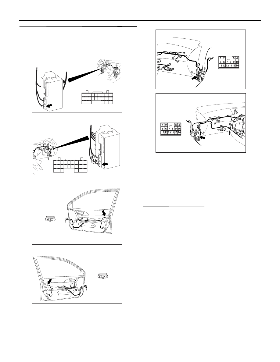
SMART WIRING SYSTEM (SWS) NOT USING SWS MONITOR
54B-295
Step 6. Check the wiring harness from E-12 door
lock key cylinder switch connector terminal
Nos.1 and 3 <LHD> or 3 and 1 <RHD> to C-227
ETACS-ECU connector terminal Nos.33 and 34.
NOTE:
Prior to the wiring harness inspection, check interme-
diate connector C-110 <LH drive vehicles> or C-17
<RH drive vehicles>, and repair if necessary.
• Check the input line for open circuit.
Q: Is the check result normal?
YES :
Go to Step 7.
NO :
Repair the wiring harness.
Step 7. Retest the system.
Check that the door lock key cylinder switch signal is
received normally.
Q: Is the check result normal?
YES :
Intermittent malfunction (Refer to GROUP
00
− How to Cope with Intermittent
).
NO :
Replace the ETACS-ECU.
AC310450
Connector: C-227
AG
Junction block
(rear view)
Harness side
<LHD>
28
37
43
29
44
38
23
32
41
24
25
26
27
34
42
36 35
33
21
22
30
39
40
31
AC310461
Harness side
Junction block (rear view)
Connector: C-227
AF
<RHD>
21
22
23
24
25
26
27
28
29
30
31
32
33
34
35
36
37
38
39
40
41
42
43
44
AC310488
Harness side
AC
Connector: E-12
<LHD>
E-12(B)
Front door (RH)
AC310498
Harness side
AB
Connector: E-12
<RHD>
E-12(B)
AC310452
Connector: C-110
AG
<LHD>
AC310454
Connector: C-17
AK
<RHD>

CHECK AT ECU TERMINAL
SMART WIRING SYSTEM (SWS) NOT USING SWS MONITOR
54B-296
CHECK AT ECU TERMINAL
M1549001200823
ETACS-ECU
NOTE: Terminal numbers 1 to 20 can not be measured as the ETACS-ECU is mounted on the junction block
directly. The values are for reference only.
AC005554 AI
C-226
C-227
C-228
Terminal
No.
Check item
Check condition
Normal condition
1
Output to the power window relay
When the power windows are
operative
System voltage
2
Power supply to the central door
locking system (battery positive
voltage)
Always
System voltage
3
Earth (for ECU)
Always
0 V
4
Ignition switch (ACC)
Ignition switch: ACC
System voltage
5
Output to room lamp
When the room lamp is on
2 V or less
6
Power supply to interior lamp
(battery positive voltage)
Always (when the interior lamp off
function is off)
System voltage
7
Input from all the door switches
One of the door switches: ON (door
open)
0 V
8
Power supply from ignition switch
(IG1)
Ignition switch: ON
System voltage
9
Output to right turn-signal lamps
When right turn-signal lamps are on System voltage
10
Input from driver's door switch
Driver's door switch: ON (door
open)
0 V
11
Power supply to turn-signal lamps
(battery positive voltage)
Always
System voltage
12
Output to central door locking (for
locking the doors)
When the door lock actuators lock
the doors
System voltage
13
Output to central door locking (for
unlocking the doors other than the
driver's door)
When the door lock actuators
unlock the doors
System voltage
14
Output to left turn-signal lamps
When the left turn-signal lamps are
on
System voltage
15 to 17 −
−
−
18
Power supply from ignition switch
(ACC)
Ignition switch: ACC
System voltage
19
−
−
−
20
Battery power supply (for ECU)
Always
System voltage
21
Input from rear fog lamp switch
Rear fog lamp switch: ON
0 V

CHECK AT ECU TERMINAL
SMART WIRING SYSTEM (SWS) NOT USING SWS MONITOR
54B-297
22
Output to central door locking (for
unlocking the driver's door)
When the door lock actuators
unlock the doors
System voltage
23 to 28 −
−
−
29
Input of collision signal
−
−
30
Input to key reminder switch
Key reminder switch: ON (ignition
key removed)
0 V
31 to 34 −
−
−
35
Input to driver's door lock actuator
(lock switch)
Driver's door lock: Locked
0 V
36
Input to driver's door lock actuator
(unlock switch)
Driver's door lock: Unlocked
0 V
37 to 44 −
−
−
51
Setting diagnosis code or sending
input check signal
When diagnosis code is set (the
M.U.T.-II/III is connected or the
diagnosis connector terminal No.1
is earthed)
0 to 12 V (pulse signal)
When input check signal is sent
0 V, 12 V (input signal
is fluctuating)
52
−
−
−
53
Output to door-ajar indicator lamp
When door-ajar indicator lamp is on 0 V
54
−
−
−
55
Input from hazard warning lamp
switch
Hazard warning lamp switch: ON
0 V
56
Earth (for sensor)
Always
0 V
57, 58
−
−
−
59
SWS communication line
Always
0 to 12 V (pulse signal)
60 to 62 −
−
−
63
Input of vehicle speed signal
When the vehicle is being driven
0 to 12 V (pulse signal)
64, 65
−
−
−
66
Input from windshield intermittent
wiper volume
Turn the ignition switch to the ACC
position, and move the wiper
volume from "Fast" to "Slow."
0 to 2.5 V
67
Input from diagnosis control
When M.U.T.-II/III is connected
0 V
68
Input of SWS request signal
Always
0 to 12 V (pulse signal)
69
Output to ignition key cylinder
illumination lamp
When ignition key cylinder
illumination is on
2 V or less
70
−
−
−
71
Power supply to interior lamp
Always (when the interior lamp off
function is off)
System voltage
72, 73
−
−
−
74
Output to rear fog lamp
When rear fog lamp is on
System voltage
Terminal
No.
Check item
Check condition
Normal condition

CHECK AT ECU TERMINAL
SMART WIRING SYSTEM (SWS) NOT USING SWS MONITOR
54B-298
COLUMN SWITCH
AC005555AG
C-206
Terminal
No.
Check item
Check condition
Normal condition
1
Battery power supply
Always
System voltage
2
Input of SWS request signal
Always
0 to 12 V (pulse signal)
3
SWS communication line
Always
0 to 12 V (pulse signal)
4
Earth
Always
0 V
5
−
−
−
6
Output to windshield intermittent
wiper volume
Ignition switch: ACC
Move the wiper volume from "Fast"
to "Slow."
0 to 2.5 V
7
−
−
−
8
Back-up output to windshield wiper
switch
Windshield low-speed wiper switch
or windshield high-speed wiper
switch: ON
0 V
9
Power supply from ignition switch
(IG1)
Ignition switch: ON
System voltage
10
Back-up output to headlamp switch Headlamp switch: ON
0 V
Нет комментариевНе стесняйтесь поделиться с нами вашим ценным мнением.
Текст