Mitsubishi Lancer Evolution IX. Manual — part 578

CLUTCH PEDAL
CLUTCH
21A-5
CLUTCH PEDAL
REMOVAL AND INSTALLATION
M1211001600340
Post-installation Operation
Clutch Pedal Adjustment (Refer to
AC310323
8
7
10
11
9
1
2
3
4
5
6
12
13
14
N
15
12 ± 2 N·m
12 ± 2 N·m
12 ± 2 N·m
16
12 ± 2 N·m
8
7
10
9
4
5
6
12
13
14
15
12 ± 2 N·m
16
12 ± 2 N·m
<LH drive vehicles>
<RH drive vehicles>
AC
Removal steps
•
Instrument panel under cover
(Refer to GROUP 52A, Instrument
panel
1.
Clutch pedal position switch
2.
Clutch pedal position switch
harness
3.
Clip
4.
Stopper
5.
Snap pin
6.
Clevis pin
7.
Clutch master cylinder mounting
nut
8.
Clutch pedal assembly mounting
bolt
>>A<<
9.
Clutch switch
10. Nut
11. Stopper
12. Pedal pad
Removal steps (Continued)
CLUTCH PEDAL
CLUTCH
21A-6
INSTALLATION SERVICE POINT
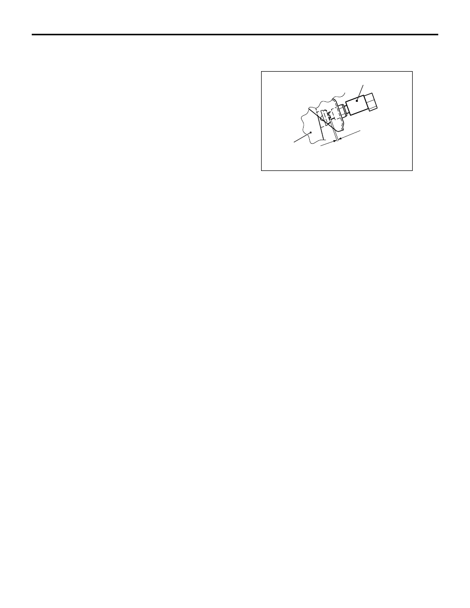
>>A<< CLUTCH SWITCH INSTALLATION
AC309757
AB
Clutch pedal
Clutch switch
0.5 – 1.5 mm
Install the clutch switch at the specified dimension
when the clutch pedal is released.
13. Pedal stopper
14. Clutch pedal assembly
15. Turn over spring
16. Bushing
Removal steps (Continued)

CLUTCH CONTROL
CLUTCH
21A-7
CLUTCH CONTROL
REMOVAL AND INSTALLATION
M1211001900396
Pre-removal Operation
• Clutch Fluid Draining
• Strut Tower Bar Removal (Refer to GROUP42, Strut
Tower Bar
Post-installation Operation
• Strut Tower Bar Removal (Refer to GROUP42, Strut
Tower Bar
• Clutch Fluid Supplying
• Clutch Line Bleeding (Refer to
• Clutch Pedal Adjustment (Refer to
<LH drive vehicles>
AC211515
12 ± 2 N·m
15 ± 2 N·m
2
8
10
11
10
18 ± 3 N·m
30 ± 4 N·m
12 ± 2 N·m
AD
11
Release fork
Release cylinder
push rod
Specified grease:
MITSUBISHI genuine grease
PART No. 0101011 or equivalent
4
3
N
5
7
1
6
9
Clutch master cylinder removal
steps
1.
Clevis pin assembly
2.
Eye bolt
3.
Gasket
4.
Reservoir hose
5.
Clevis pin and pushrod assembly
connecting part
6.
Clutch master cylinder
7.
Sealer
8.
Retainer plate
Clutch release cylinder removal
steps
10. Clutch pipe
11. Clutch release cylinder
Clutch line removal steps
9.
Clutch hose
10. Clutch pipe

CLUTCH CONTROL
CLUTCH
21A-8
<RH drive vehicles>
AC310343
15 ± 2 N·m
6, 8
7
Release fork
Release cylinder
push rod
Specified grease:
MITSUBISHI genuine grease
PART No. 0101011 or equivalent
AB
2
8
18 ± 3 N·m
12 ± 2 N·m
4
3
5
7
1
6
9
Clutch master cylinder removal
steps
1.
Clevis pin assembly
2.
Clutch pipe connection
3.
Reservoir hose
4.
Clutch master cylinder
5.
Sealer
Clutch release cylinder removal
steps
6.
Clutch pipe
7.
Clutch release cylinder
Clutch line removal steps
8.
Clutch pipe
9.
Clutch hose
INSPECTION
M1211002000169
• Check the master cylinder or clutch hose for fluid
leakage.
• Check the clutch hose or tube for cracks or clog-
ging.
Нет комментариевНе стесняйтесь поделиться с нами вашим ценным мнением.
Текст