Mitsubishi Lancer Evolution IX. Manual — part 103

HOW TO USE TROUBLESHOOTING/INSPECTION SERVICE POINTS
GENERAL
00-5
HOW TO USE TROUBLESHOOTING/INSPECTION SERVICE
POINTS
M1001000201143
CONTENTS OF TROUBLESHOOTING
Troubleshooting of electronic control systems for which the M.U.T.-II/III can be used follows the basic outline
described below. Even in systems for which the M.U.T.-II/III cannot be used, some of these systems still fol-
low this outline.
STANDARD FLOW OF DIAGNOSIS TROUBLESHOOTING
Troubleshooting sections are based on the diagnostic flow as below. If the diagnostic flow is different from
that given below, or if additional explanation is required, the details of such differences or additions will also
be listed.
Diagnosis method
AC300864AE
Gathering information
from the customer.
Check trouble symptom.
Read the diagnosis code.
Read the diagnosis code.
Refer to the TROUBLE
SYMPTOM CHART (Refer to
applicable group.)
Refer to the DIAGNOSIS CODE
CHART (Refer to applicable
group.)
INTERMITTENT MALFUNCTIONS
After taking note of the
malfunction code, erase the
diagnosis code memory.
Recheck trouble symptom.
Read the diagnosis codes.
Reoccurs
Does not reoccur
Diagnosis code
displayed.
Diagnosis code
displayed.
Diagnosis code
displayed.
No diagnosis code
or communication
with M.U.T.-II/III
not possible
No diagnosis
code.
No diagnosis
code.
SYSTEM OPERATION AND SYMPTOM
VERIFICATION TESTS
If verification of the symptom(s) is difficult, proce-
dures for checking operation and verifying symptoms
are shown.
DIAGNOSIS FUNCTION
Details which are different from those in the "Diagno-
sis function " section are described.
DIAGNOSIS CODE CHART
Diagnosis codes and diagnostic items are shown.
DIAGNOSIS CODE PROCEDURES
Indicates the inspection procedures corresponding to
each diagnosis code (Refer to How to read inspec-
tion procedure
).

HOW TO USE TROUBLESHOOTING/INSPECTION SERVICE POINTS
GENERAL
00-6
TROUBLE SYMPTOM CHART
If there are trouble symptoms even though the
M.U.T.-II/III does not find any diagnosis codes,
Inspection procedures for each trouble symptom will
be found by means of this chart.
SYMPTOM PROCEDURES
Indicates the inspection procedures corresponding to
each symptom classified in the Symptom Chart
(Refer to How to read inspection procedure
).
SERVICE DATA REFERENCE TABLE
Inspection items and normal judgment values have
been provided in this chart as reference information.
CHECK AT ECU TERMINALS
Terminal numbers for the ECU connectors, inspec-
tion items, and judgment values have been provided
in this chart as reference information.
INSPECTION PROCEDURE BY USING AN
OSCILLOSCOPE
When there are inspection procedures using an
oscilloscope, these are described here.
DIAGNOSIS FUNCTION
HOW TO READ DIAGNOSIS CODE
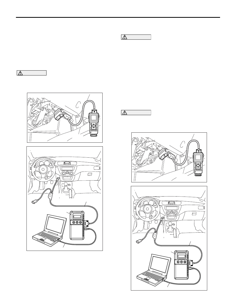
CAUTION
Before connecting or disconnecting the
M.U.T.-II/III, turn the ignition switch to the "LOCK"
(OFF) position.
<Using the M.U.T.-II>
AC304777
Steering shaft
AB
MB991502
<Using the M.U.T.-II>
Connect the M.U.T.-II to the diagnosis connector,
and read the diagnosis code.
<Using the M.U.T.-III>
AC211686
MB991911
16-PIN
MB991827
MB991824
AE
<Using the M.U.T.-III>
Connect the M.U.T.-III to the 16-pin diagnosis con-
nector, and read the diagnosis code.
NOTE: For details on how to use the M.U.T.-III, refer
to the "M.U.T.-III operation manual."
1. Ensure that the ignition switch is at the
"LOCK" (OFF).
2. Start up the personal computer.
3. Connect M.U.T.-III USB cable MB991827 to
special tool Vehicle Communication Interface
(V.C.I.) MB991824 and the personal compu-
ter.
4. Connect M.U.T.-III main wiring harness B
MB991911 to the V.C.I.
5. Connect M.U.T.-III main wiring harness B to
the diagnosis connector.
6. Turn the V.C.I. power switch to the "ON" posi-
tion.
NOTE: When the V.C.I. is energized, the V.C.I.
indicator lamp will be illuminated in a green
colour.
7. Start the M.U.T.-III system on the PC and turn
the ignition switch to the "ON" position.
8. Read the diagnosis code.
9. Disconnecting the M.U.T.-III is the reverse of
the connecting sequence, making sure that
the ignition switch is at the "LOCK" (OFF).
HOW TO USE TROUBLESHOOTING/INSPECTION SERVICE POINTS
GENERAL
00-7
NOTE: The ABS warning lamp may flash when the
ignition switch is turned ON with the M.U.T.-II/III con-
nected. This is because the diagnosis display func-
tion of the ABS warning lamp is activated by earthing
the diagnosis connector terminal No.1, and is not
detrimental in any way.
ERASING DIAGNOSIS CODE (BY USING
THE M.U.T.-II/III)
CAUTION
Before connecting or disconnecting the
M.U.T.-II/III, turn the ignition switch to the "LOCK"
(OFF) position.
AC304777
Steering shaft
AB
MB991502
<Using the M.U.T.-II>
AC211686
MB991911
16-PIN
MB991827
MB991824
AE
<Using the M.U.T.-III>
Connect the M.U.T.-II/III to the diagnosis connector,
and erase the diagnosis code. The procedure is the
same as "HOW TO READ DIAGNOSIS CODE ".
ERASING DIAGNOSIS CODE (BY USING
NO M.U.T.-II/III)
CAUTION
Some diagnosis codes can not be erased accord-
ing to the procedure below. If you attempt to
erase a diagnosis code, refer to an applicable
GROUP.
1. Turn the ignition switch to the "LOCK" (OFF)
position.
2. Disconnect the negative battery cable, wait for at
least 10 minutes, and then reconnect it.
3. Start the engine and let it run at idle for 10
minutes.
INPUT SIGNAL CHECK (WHEN USING
THE M.U.T.-II/III) <SWS>
CAUTION
Before connecting or disconnecting the
M.U.T.-II/III, turn the ignition switch to the "LOCK"
(OFF) position.
AC304777
Steering shaft
AB
MB991502
<Using the M.U.T.-II>
AC211686
MB991911
16-PIN
MB991827
MB991824
AE
<Using the M.U.T.-III>
HOW TO USE TROUBLESHOOTING/INSPECTION SERVICE POINTS
GENERAL
00-8
1. Connect the M.U.T.-II/III to the diagnosis
connector, and erase the diagnosis code.
2. If the M.U.T.-II/III buzzer sounds once when each
switch is operated (ON/OFF), the input signal for
that switch circuit system is normal.
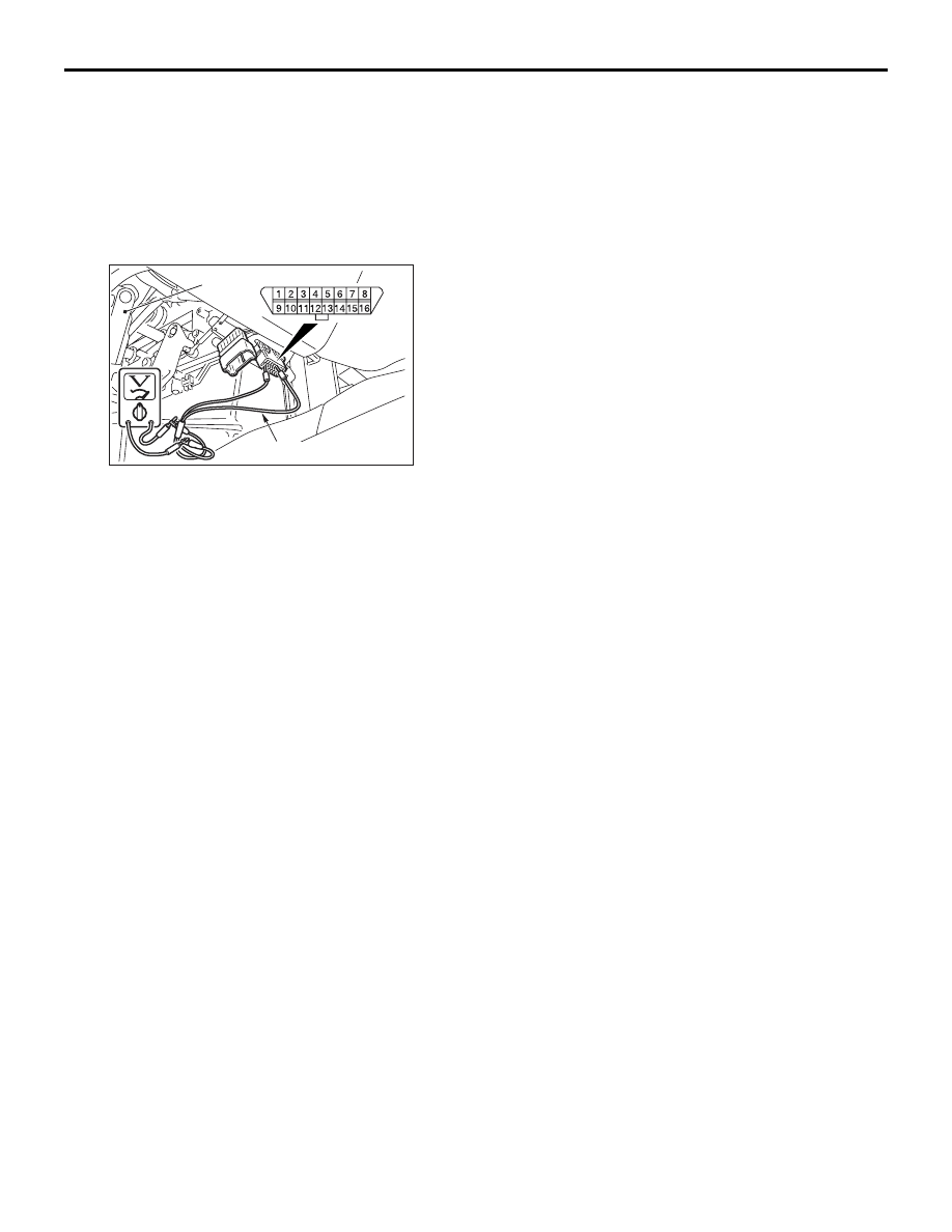
INPUT SIGNAL CHECK (WHEN USING A
VOLTMETER) <SWS>
AC304779AB
Steering
shaft
MB991529
1. Use the special tool diagnosis code check
harness (MB991529) to connect the ETACS
terminal (terminal 9) and the earth terminals
(terminals 4 and 5) of the diagnosis connector to
the voltage meter.
2. If the needle of the voltage meter flickers once
when each switch is operated (ON/OFF), the input
signal for that switch circuit system is normal.
Нет комментариевНе стесняйтесь поделиться с нами вашим ценным мнением.
Текст